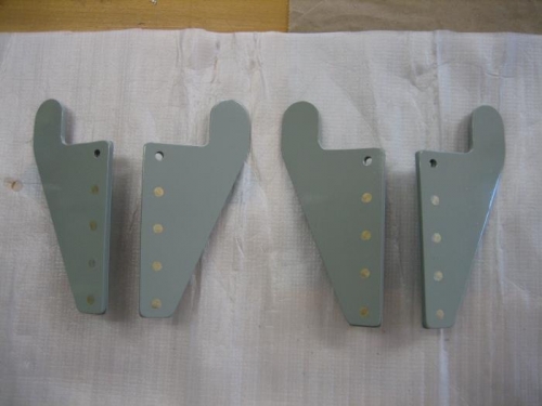
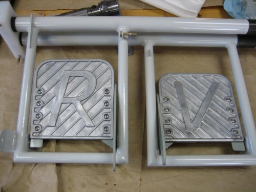
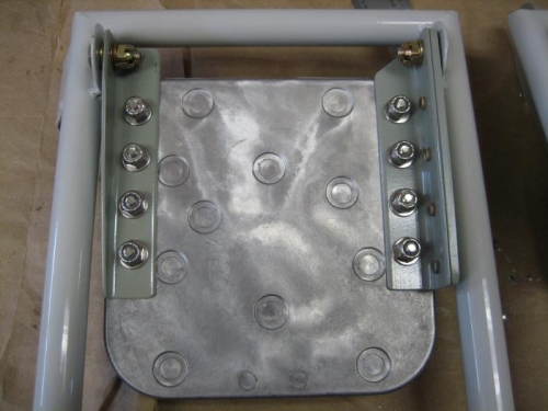
I had already made the F-6117A brake pedal side plates and the F-6117C angles. Now it was time to debur, prime and paint the pieces. I went through the usual steps that I have done several times in the past. I hung the parts to dry and moved on to the brake pedals. Instead of using Van's pedals, I had purchased cast aluminum pedals with the RV logo and instead of riveting the pedals to the side plates I planned on using SS screws with lock nuts. I laid the two WD-655-L/R brake pedal support weldments on my bench and placed the pedals in position to give me an idea where to drill the holes for the screws. The pedals already had holes so I would need to transfer those to the 4 angles I had just painted. Before I could do the transfer I would have to rivet the 2 brake side plates to the 2 angles with AN426AD4-6 rivets. I used my pneumatic squeezer to rivet the parts together. With the brake side plates riveted I clamped the plates to the rudder pedals and match drilled the holes through the angle. I did the same with the 2 angles. I deburred the holes and using SS screws attached the brake side plates and angles to the pedals. Next I deburred the holes in the rudder pedal weldments with a ream for a nice tight fit for AN3 bolts. I bolted the rudder pedals to the weldments with AN3-5 bolts and related hardware as called for in DWG 37.