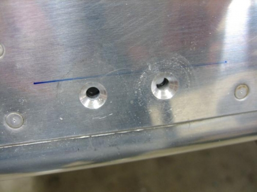
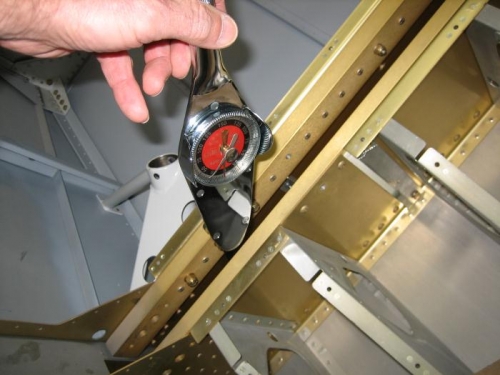
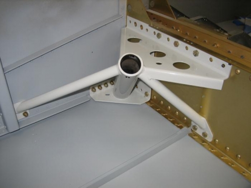
I reinstalled both landing gear weldments so I could machine countersink the two forward side #12 holes to accept AN509-10R12 screws as called for on DWG 34A. I used a #12 100 degree countersink bore. I removed both gear weldments and deburred the holes and reinstalled the gear weldments for the last time. I inserted all the bolts as called for in DWG 34A. The spar box was a little difficult to get the washers and nuts on due to the tight space. I used a long piece of scotch tape to hold the washer or nut and lowered it to the end of each bolt. I used a long piece of bar stock to push the washers and nuts onto the bolts. I was able to turn the nuts and get them started onto the threads. The weldment is held in place with AN3 and AN4 bolts and torqued to standard specifications. My Snap-On torque wrench would not fit in most locations on the gear weldment so I had to use an extension. The torque manual has a formula for calculating the correct torque when extensions are used. I also had to add the torque of the AN365 nut to the calculation. I made my first pass on the nuts and then came back and double checked the torque.