Brief Description: Installing Switches on to the Insturment Panel
Lightly sanded the red center areas on the outer wheel covers. Bushed on a coat of red paint on both wheel covers and set them aside to dry.
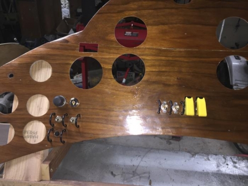
Evaluated the position of the proposed switch installation on the instrument panel. Found that there would not be enough space under the transponder's position to fit the four switches. Moved the transponder to the right under the VSI and moved the switches up to fit in the space available. Marked the back of the panel in 1 inch intervals starting from the center. The switch holes were drilled in the center of the interval with a step drill. The two right switches have yellow guards and are the left and right ignition switch and are on when the guards are down. Loop guards were installed around the two left switches. One switch is for emergency power to the ignition and the other is the electric fuel pump. On the left side five switches were installed. The top left is the starter push button. On the right of the starter switch is the keyed master power switch. The beacon and avionics master switches are the next two switches installed below the starter button. The last switch installed below the beacon switch is for the electric scavenge pump. Loop switch guards are installed around the three toggle switches.
The red center area of the outer wheel covers was lightly sanded with 1000 grit sandpaper. The mini roller was used to apply a coat of red paint to the center area of the wheel covers. The covers were set aside to dry until tomorrow.