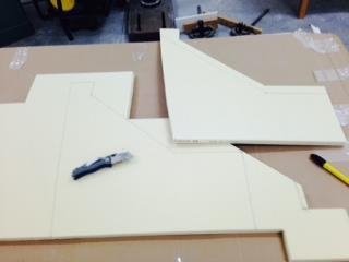
I measured and marked the shape of the right side aft end spacer on the LAST-A-FOAM then used a utility knife to cut it out. I then traced this piece onto the right fuselage side so I will know later where to apply the microslurry. I also marked the bottom of the fuselage shape on this piece then cut it out as well.
I used this piece to trace the outline of the 2nd piece onto the LAST-A-FOAM then I used a utility knife to cut it out as well. Next I traced the shape onto the left fuselage side so I will know later where to put the microslurry.
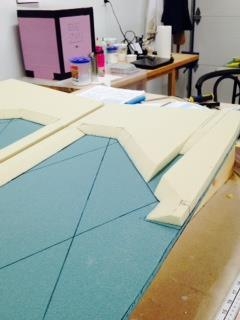
I took a piece of scrap foam and cut a shortened version of a 3" spacer as per EE in diagram 7 and used a saw to cut it to shape making the beveled edge. This piece is just used to help me align the bottom of the aft end spacers so they will align later with spacers EE .
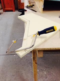
I positioned the right side aft spacer on the fuselage side and measured/marked where I needed to bevel the edges to align with spacers CC, EE, and to match figure 7. I used the CC profile to bevel the edges up to the elbow at the bottom then I switch over to the EE profile (after the 18" as per fig 7). I used a hand saw to slowly bevel the edges and sanded where needed.
I repeated this with the left side aft spacer.
Next I measured and marked profiles GG and HH on the right side aft spacer. I used a utility knife to cut out the open segment then I used a hack saw to cut the ramp up to the aft end. I tried a chisel to dig out the slope (as per the manual) but that wasn't working very well so I used the utility knife to carefully remove material to make a rough slope then I used a piece of LAST-A-FOAM to sand the slope.