Brief Description: Stall Warning Switch Assembly and Installation
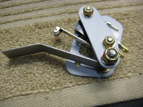
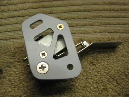
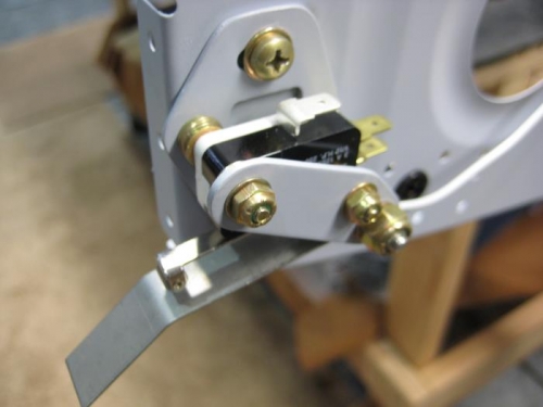
Completed step 4 page 16-02 – assembled stall warning switch per Figure 1. Completed step 5 – fabricated WH-B217 ground wire and installed ES-DV188-M female spade on one end and ES-31890 ring terminal on the other end of a 5 inch long #18 wire. Completed step 6 – installed stall warning subassembly on the W-1208-R nose rib per Figure 2 attaching to the two previously installed nut plates. Completed step 7 – installed W-1202-L wing skin per Figure 3 for adjustment of the stall warning switch. Completed step 1 page 16-03 – adjusted stall warning switch per Figure 1 for minimum travel actuation travel. Had to remove skin several time to make adjustments and also needed to bend the switch arm as noted in the plans. Got the switch so that it would actuate within the travel available within the slot in the wing skin. In at rest position stall warning arm is touching the bottom of the slot. Completed step 2 and removed the W-1202-L mid wing skin after adjustments were completed. Checked the mounting screws were tight for final location