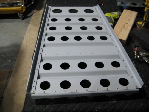
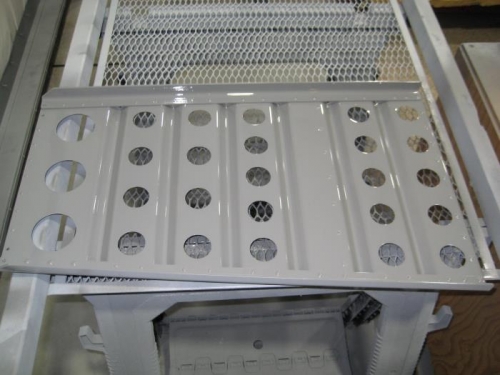
Completed steps 1-7 page 25iS/U-04 for both seats - primed and painted. Step 1: Clecoed the locating hole in the 12 1/2 [317.5 mm] half of the F-1237F to the F-1237A per Figure 1. Centered the line drawn on the F-1237F with the holes in the F-1237A, then firmly clamped the parts together. Step 2: Match-Drilled #30 the holes in the F-1237A into the F-1237F. Clecoed each hole as it is drilled and continued to verify that the line on the F-1237F remains centered on the holes in the F-1237A as drilling progressed. Step 3: Marked the F-1237F and F-1237A so that they can be reassembled in their original configuration. Disassembled the parts and deburedr the holes. Step 4: Clecoed the F-1237F to the F-1237A as previously marked, then riveted the parts together using the rivets called out in Figure 1. Placed the manufactured heads of the rivets against the F-1237A. Step 5: Clecoed the F-1237B, F-1237D, and F-1237C-L & -R to the F-1237A. Step 6: Final-Drilled #12 the two holes in both lower corners of the Seatback Assembly for the indicated bolts. Disassembled the Seatback Assembly and deburred the holes. Step 7: Clecoed the F-1237B, F-1237D, and F-1237C-L & -R back onto the F-1237A, then riveted the parts together using the rivets called out. Placed the manufactured head of the rivets on the forward side of the Seatback Assembly.
Completed step 1 page 25iS/U-05 for both seats Step 1: Cut a 14 1/2 in. [368.3 mm] length from one of the hinge pins that was previously set aside. Measures 1 in. [25.4 mm] from one end of the hinge pin and make a 90° bend as shown in Figure 2. Filed the other end of the hinge pin to make a dull point.