Brief Description: Rollover Structure and F-01207 bulkhead
Completed steps 1-4 and 6 page 24iS/U-04
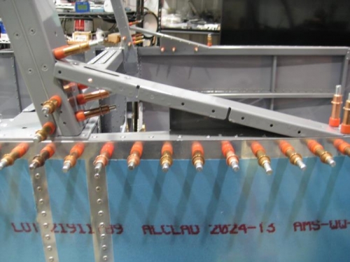
Step 1: With the Roll Bar Assembly clecoed to the forward face of the F-1231D's, clecoed the Roll Bar Support Assemblies to the Roll Bar Assembly and F-01234-L-1 & -R-1 as shown in Figure 1. Step 2: Match-Drilled #30 the twelve holes in the sides of the Roll Bar Assembly into the F-1231D's. Step 3: Removed, deburred, primed, and loosely reattached the F-1231D's to the F-01205B-L-1 & -R-1. Step 4: Clecoed the Roll Bar Assembly to the F-1231D's per the call-outs in Figure 1. Riveting on hold awaiting for LP4-4 rivets to arrive. Step 6: Tightened the bolts securing the F-1231D's and torque stripped them
Completed step 4 - page 24iS/U-05 Step 4: Riveted the ES-00301 onto the F-01207C-L-1 using the hardware called out in Figure 1.
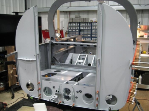
Completed steps 1-12 page 24iS/U-06 Step 1: Clecoed the F-12110 to the aft face of the F-01207C-L-1 using the two holes shown in Figure 1. Step 2: Match-Drilled #30 the five remaining holes in the F-12110 into the F-01207C-L-1. Step 3: Removed the F-12110 from the F-01207C-L-1 and deburred. Step 4: Riveted the F-12110 to the F-01207C-L-1 as directed in Figure 1.
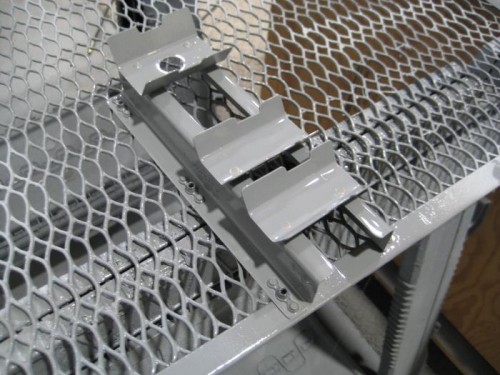
Step 5: Dimpled the nutplate attachment holes in the F-12111A-L & -R for flush rivets on the forward side of the flange. Step 6: Separated the F-12111C into two individual parts, then machine countersunk for the rivets called out in Figure 2. Step 7: Riveted the two F-12111C's and then the F-12111B to the F-12111A-L & -R as shown in Figure 2 to create the Fuel Pump Bracket Assembly. Step 8: Riveted only the bottom nutplates to the F-12111A-L & -R as shown in Figure 2.
Step 9: Inserted the tabs at the top of the Fuel Pump Bracket Assembly into the slots in the F-12110, and secured the bottom of the Fuel Pump Bracket Assembly to the F-1207C-L-1 using #8-32 screws per Figure 3. Step 10: Match-Drilled the four remaining nutplate screw holes in the flanges of the Fuel Pump Bracket Assembly into the F-01207C-L-1 as indicated in Figure 3. Step 11: Removed the Fuel Pu