Brief Description: Roll bar assembly and parts prep
Completed steps 4 and 6 psge 23iS/U-03
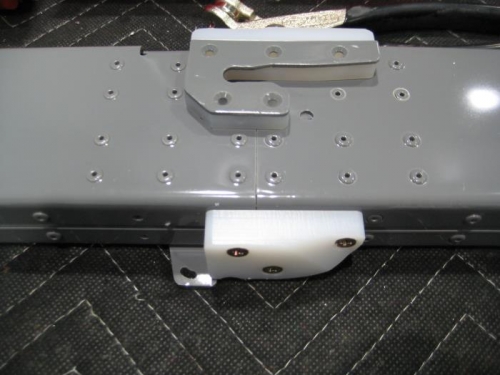
Step 4: Tapped #8-32 the three holes in the Roll Bar Assembly for the screws shown in Figure 2. The C-01205-2 was used to help keep the tap square to the bottom surface of the Roll Bar assembly: Inserted the tap through one of the two holes in the thicker portion of the C-01205-2, centered the end of the tap on the hole in the Roll Bar Assembly, slid and held the C-01205-2 flush against the bottom of the Roll Bar Assembly, then tapped the hole. Repeaedt for the remaining two holes. Step 6: Machine countersunk the C-01205-2 for the heads of the screws, then installed it with the hardware shown in Figure 2.
Completed steps 1-3 and 5 page 24iS/U-05
Step 1: Marked a line on the forward face of the F-1284-L & -R as dimensioned in the Detail View of Figure 1. Step 2: Clecoed the F-01207C-L-1 & -R-1 to the Tailcone Assembly as shown in Figure 1. Step 3: Centered the lines drawn in Step 1 in the two indicated holes in the F-01207C-L-1 & -R-1, then clamped in place and match-drilled #30 from the F-01207C-L-1 & -R-1 into the corresponding F-1284-L & -R perFigure 1. Removed the clecos and deburred the holes then primed the parts
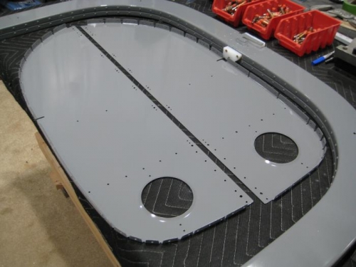
Completed step 7 page 24iS/U-04 Step 7 (912iS Only): Final-Driledl #19 the two indicated holes in the aft flange of the F-01224-L-1 Baggage Floor. These two holes correspond to the two holes final-drilled in the F-01207C-L-1 on the next page
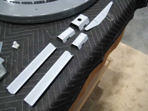
Deburred and primed parts for assemblies on page 24iS/U-06, 07