Brief Description: Installation of Fuselage Mid Brace
Completed steps 3-5 page 23iS/U-03
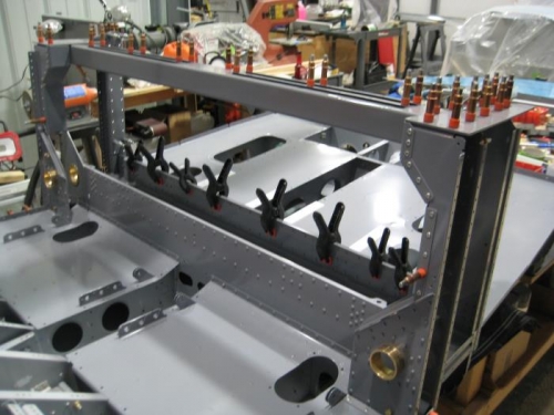
Step 3: Riveted F-01205A-1 to the aft side of F-01204B-L-1 & -R-1 per Figure 2. Step 4: Riveted F-01205B-L-1 & -R-1, F-01204K-L & -R and F-01205C-1 to F-01205A-1 and F-1204C-L & -R per Figure 2. Step 5: Riveted F-01205D and F-01205E onto the F-01205A-1 as shown in Figure 2 (only the right side is shown, mirrored what is shown for the left).
Completed steps 1 - 7 page 23iS/U-04 for both sides
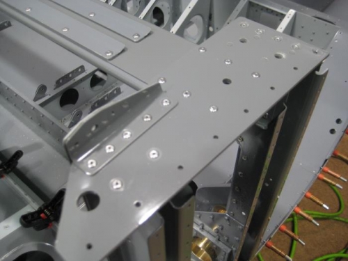
Step 1: Machine countersunk the rivet holes in one of the F-01204J to create a right hand part as shown in Figure 1. Step 2: Riveted the F-01204J-R to the F-01204F-R-1, F-01204G-R, and F-01204K-R as shown in Figure 1.
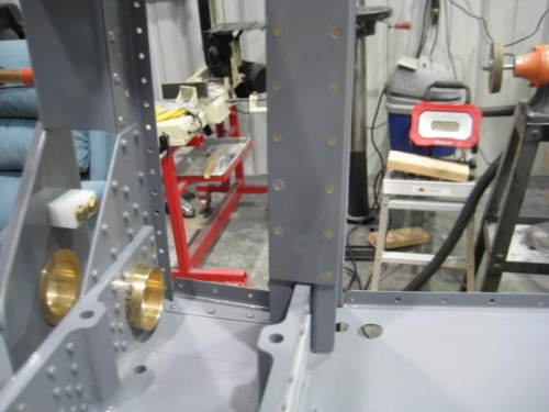
Step 3: Cut apart then deburred F-1203H-L & -R as shown in Figure 2. Step 4: Dimpled the two holes in the end of F-1203G-R as indicated in Figure 3. Step 5: Riveted F-1203H-R to F-1203G-R as shown in Figure 3. Step 6: Dimpled the holes in F-01234-R-1 except as indicated in Figure 4. Step 7: Machine countersunk the match-drilled holes in F-01255-R-1 that correspond to the holes just dimpled in F-01234-R-1. Step 8: Removed the tab from the notch in F-01248-R-1 as shown in Figure 5. Step 9: Repeated and mirror Steps 1 through 8 for the left side.