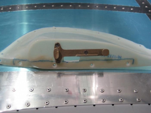
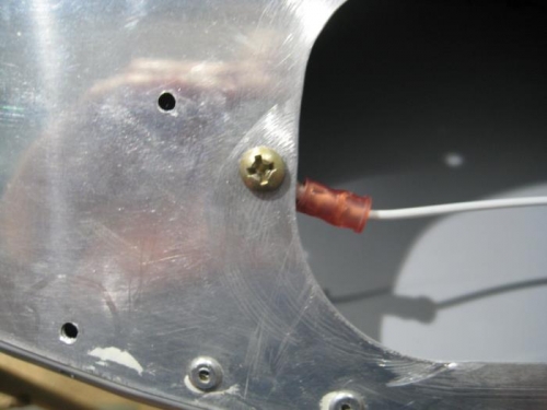
Completed steps 1 thru 6 page 40-09 for the right hand wing strobe. Clamped the mount bracket in place on each extension, then match-drilled #27 the holes in the mount bracket into the extensions. Removed material from the W-1222-L & -R Extensions inside the shaded oval area shown in Figure 1. Performed machine countersink 120° all the attach holes in the upper flange of the W-1222-R Extension for the head of a CS4 rivet. Finished the edges of the part. Step 4: Attached the LN-200 Wing Tip Nav/Position/Strobe Light -Set mount brackets to the W-1222-L & -R extension using the hardware shown in Figure 1. Cut one piece of 18 gauge wire 6 inches long. Stripped both ends of the wires. On one end of the wire crimped the ring terminal shown in Figure 2. On the remaining end of the wire crimped a female Molex pin. Attached the ring terminal on the end of the WH-B211 (WHT) Nav/Strobe Ground Wires to the hole in the W-1204D Wing Tip Close-Outs using the hardware called out in Figure 2.