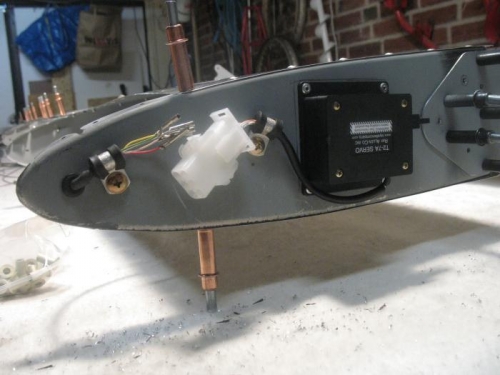
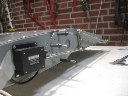
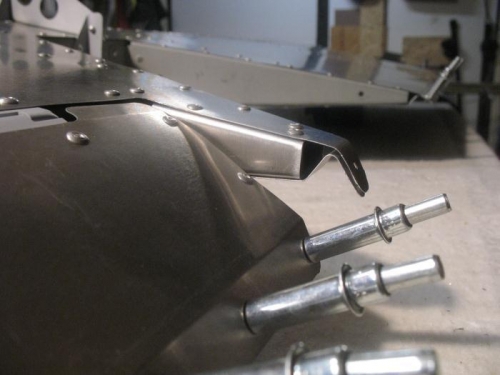
The manual is diveded into two parts and for some reason the trim servo assembly is located in chapter 1 part 2 while the trim tab assembly is located in part 1, chapter 11. No sweat, but it takes a lot of scrolling in the manual. The illustrations are quite good so it's not very difficult to find out how the servo and the servo rods should be attached. Before rivetting the servo unit to the left rib the servo rods were attached and the trim tab was set to 30 mm nose down which is the recommended power off deflection for the Savannah with a Rotax 912 engine. This position of the servo unit relative to the rib was marked and then rivetted in place on the rib. I assume that this will be fine provided that the servo unit is in "power off" position when delivered. The two wires to and from the servo was clamped to the rib to secure the two connectors. Here is a problem that I need to fix later:The five wires from the servo to the connector are marked white/white/white-red/white-blue/white-green whlie the wires to the connector are marked white/grey/red/yellow/green. So which goes where? Well, fortunately this was easy cleared by ICP who kindly sent me a drawing that explained it all.