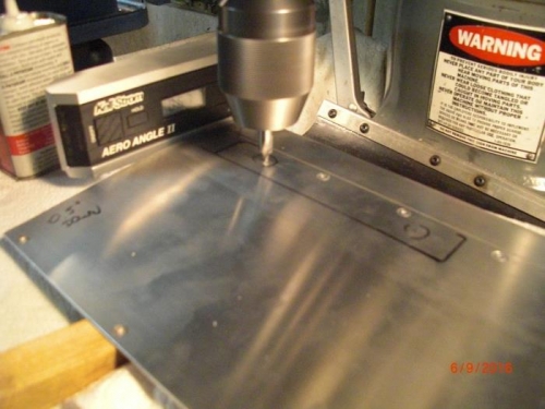
Next is securing tip weights into the rotor. I was concerned that the camfers for he screws would wander off, so I decided to do this operation on my Bridgeport.I built a table extension so I coud put the complete blade on the mill table. I marked the hole locations, clampled the tip weight into position so it woud not move during drilling. Also wanted to make sure screw heads would be as flush as possible with the blade surface. I stuck a 1"x1/2" pice of steel into the spar so I could lay my digital protractor on it to adjust the positon of the blade on the mill table and then clampl the blade carefully in place making sure I was not bending anything. The process was: - Use small cener drill to locate hole. - Follow with bg 1/2" center drill and create 1/2" diameter chamfer with it -Use 5/8" sinker to enlarge chanfer to appropriate diameter to have screw head flush with surface - drill core hole with #7 drill as deep as possible into tip weight, but not drilling into spar below weight. -Take tip weight out of rotor blade and drill #7 hole all the way through tip weight -Reinstall tip weigh -Start tapping 1/4"x20 thread using mill head assuring desired thread alignment with blade surface -Disassemble and finsh thead in tip weight. -Install tip weights and install flush head screws to secure weights in blade.