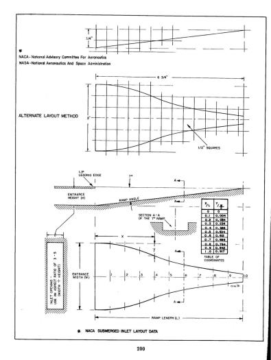
The NACA air scoop for the cockpit ventilation was modeled after the template attached in image 1. The template has a 2" wide and 3/4" height entrance throat and 5" long ramp. A paper template was used to locate the vent on the inside of the nose cone. The vent hose connection was kept forward of the brake connections to avoid any conflict with the pilot or co pilot's feet. The centerline of each vent is parrallel to the centerline of the aircraft. It was located such that the ramp entrance was just inside of the main curvature of the exterior fuselage.
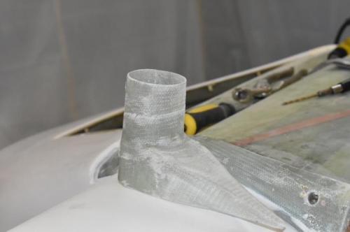
A mold in the shape of the vent scoop was made using urethane foam. It was made about 1" taller than the actual scoop to allow a cut to be made for the final height on a straight side avoiding the excess BID that curved outward. Two BID were layed up over the mold and allowed to cure. This was completed for two vents. After cure, the foam was removed and the vent height cut to maintain the 3/4" entrance height.
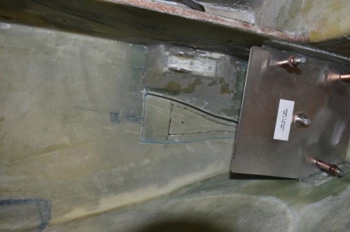
Another 1 1/2" ID PVC pipe was used to make FRP tube. Once cured, it was cut in half for the two vents. The FRP tube was cut to allow a portion of the tube to cover the rear of the pressure recovery cavity. The front part of the tube was limited to the front entrance lip. A hole was cut on the vent for the tube. A portion of the back of the vent scoop was also cut out to open up the full tube ID. About 0.25" was left at the bottom to provide a glue surface between the tube and the scoop. Two BID tapes were used to fasten the tube to the vent.