
|

|
|
|
GA Aerospace’s Web Site
|
Date: 6-6-2018
|
Number of Hours: 6.00
|
Manual Reference:
|
Brief Description: Page 40-08 and 40-0-10 completed (Completed wings
|
|
**Page 40-08** we completed the following steps (and the whole page):
7. To drill these two holes, we first used a #40 drill bit then expanded them with the #30 one.
8. We used a dremel, moto tool and bench sander.
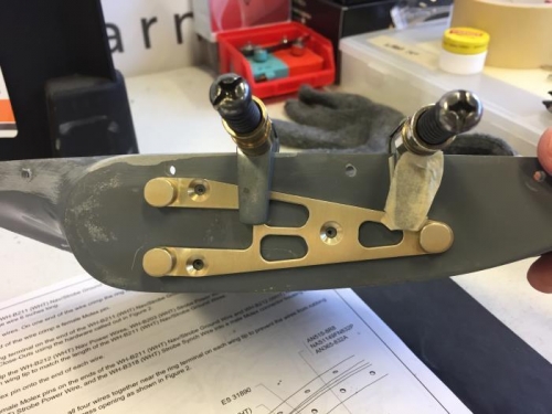
On **Page 40-09**(page completed):
1. We marked the dimple holes with a bit of marker to make them more visible, then we used cleco clamps to hold the mount brackets in position, drilled #40, putting a cleco for each hole, then 2 clecos we removed the clamps, after that expanded to #27 with the mount on place.
2. N/A
3. There’s one hole that we countersunk manually, that is the second to last most outboard hole.
4. Make sure that, once mounted, you are still able to fit a riveter for the CS4-4 rivet that’ll go right next to the mount bracket.
7. N/A
8. Just to have an order we inserted the pins to the housing in the following sequence Ground-B203-B212-B318 for the right wing and B318-B212-B203-Ground on the left wing (when the wings are upside, down)
9. N/A
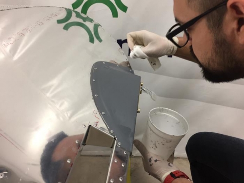
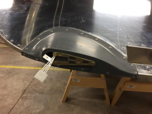
On **Page 40-10**:
1. N/A
2. We did not use electrical tape
3. We did not use electrical tape
4. N/A
5. N/A
6. We did not use a stick, we used a different tool.
7. N/A
9. N/A
10. N/A
11. N/A
12. N/A
13. We did this step differently, there’s only one way the connector can fit, the cables are labeled.
We have to wait one day for the sealant to dry, step 14 will be completed then.
|
|
|
|
|
|
|
|
|
|
|
|
|
|
|
Copyright © 2001-2024 Matronics. All Rights Reserved.
|