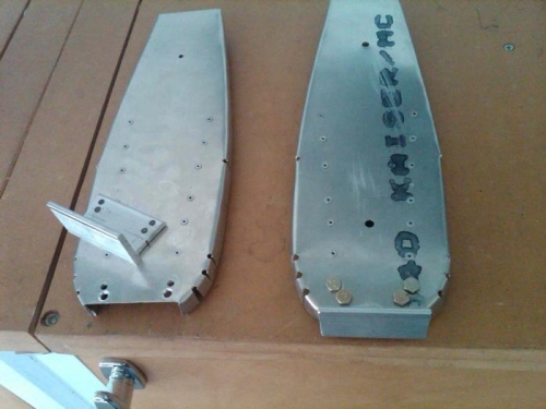
Brief Description: Rermade F-12 and tail wheel bracket
Cut and drilled new blank and shapred new F-12. Cut and shaped 3/4" x .062 angles and riveted to F-12. Cut new tail wheel bracket and carefully laid out mounting holes. Assembled tail wheel bracket to F-12. Reused to AN3-4A bolts and AN365 Nylock nuts, so added a bit of seizing to secure those nuts
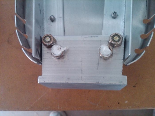
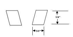
The fit up of the tail wheel bracket must be cut to fit between the two 3/4" angles. As shown in the drawing below, there is only a trapezoidal area about 3/4" x 5/8" to fit two 3/16" machine screws and keep their heads from interfering. Tailwheel bracket must fit snug between the angles to give maximum material for the bolt holes. After trimming the bracket to fit I made a template and checked the layout of the bolt heads before drilling the holes in the bracket.