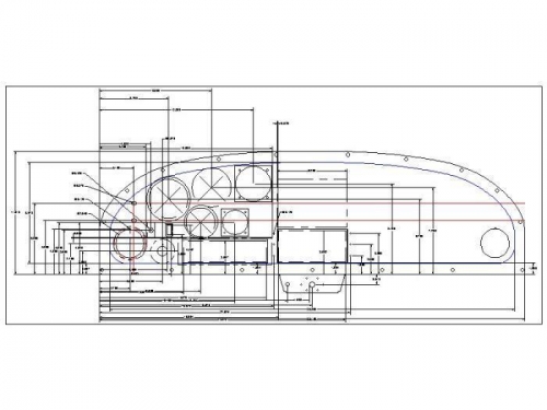
I started the panel layout as I planned to locate the Radio Mount plates on the panel using the tray for my transponder to set the proper spacing between the mount plates. I began the panel layout on CAD using the .dxf file available from the Rans website.
As you can see on the image attached I am going with analog gauges and a tradional panel design. The radio stack will contain a Garmin 327 transponder, Garmin 200 radio/intercom and a Garmin 660 in a Gizmo dock. Large rectangular cutout in front of the pilot is for a Composite Design MP-2 switch panel. I determined the location for the six rivet holes for the radio mount plates in the panel.
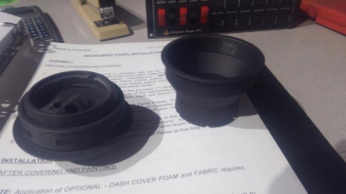
During this design work I noted that the figures manual called out a 4 screw pattern for retaining the eyeball vents while the .dxf file didn't have these holes. I pulled the part and sure enough the eyeball vents included in the kit did not use the retaining screws, instead having a screw on collar. So check your parts to see what you have.
I also used the Garmin 327 installation drawing to locate and drill the radio mount plates for installation of the transponder tray.