Brief Description: Rough Fitting of the Door Shells
SECTION 45: CABIN DOORS & TRANSPARENCIES SECTION 45-02 Step 1, after locating the C-1002A-L/R Outside Door Shells I drilled the four inside reference holes and the tow fwd and aft index holes with #40 drill bit. Then according to the A-A section I marked ¾” and 1-1/4” lines around the inside of the window perimeter. The on the 1-14/4 mark I further marked every 1-1/2” a slight mark with a green marker. Then I drill with a #40 drill bit all the green marks. The trimmed the inside and outside of the perimeters with-in the tolerances of section A-A. Step 2, Just as in the Outside Shell the Inside Shells C-1002B L/R Cabin Inter Shells had six dimpled holes that I drilled with a #40 size bit. Then trimmed the inside and outside of the Cabin Door Inner Shells according to Section B-B. Finally, sanded both the C-1002A-L/R Outside Door Shells and Shells C-1002B L/R Cabin Inter Shells with #80 grit sand paper where specified in both Figures 1 and 2. Time about 2 hours.
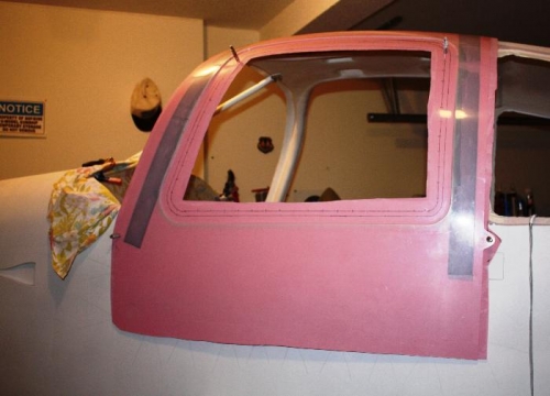
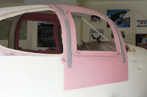
SECTION 45-03 Step 1, Since I don’t have a hole finder tool I followed the instructions and Figure 1 by drawing lines on the X-10’s fuselage that intersect at the rivet holes that were deliberately left open to help in the fiberglass (gluing) the C-1002A-L/R Outside Door Shells and Shells C-1002B L/R Cabin Inter Shells together. Step 2, Using the four inner #40 holes I clecoed the C-1002A-L/R Outside Door Shells and Shells C-1002B L/R Cabin Inter Shells together. Step 3, Then placed the Left Door in its intended place and clecoed the C-1002A-L/R Outside Door Shells and Shells C-1002B L/R Cabin Inter Shells to the fuselage using the fwd and aft index holes. However, during construction of the Fuselage my kit did not contain any visible scribe marks. So I have waited until now to remove the return flange. The plans call for a 1/16” to 1/8” rough gap between the C-100b L/R Door Inner Shell and the return Flange. In my case I have a way to go before obtaining the rough estimate.