
|

|
|
|
Conrads X-10 Build Log
|
Date: 1-3-2010
|
Number of Hours: 2.00
|
Manual Reference: 37-3 Steps 1 to 9
|
Brief Description: Section 37 FUEL SYSTEM page 37-3 Steps 1 to 9
|
|
Section 37 FUEL SYSTEM page 37-3 Steps 1 to 9
Step 1, After locating the ATO-035X3/8” aluminum tubing I cut tow fuel lines 10.5 inches long.
Step 2, Insert a AN818-6D nut and AN819-6D sleeve onto one end of the just cut fuel line and then flair one end.
Step 3, Bend the fuel line into a 90 degree angle that has one side 5-3/4” and 5-21/32” then slide on the same hardware as in step 2 and flare the end.
Step 4, I added the two created 10.5 inch fuel lines to the completed VA-178G Fuel Valve and to the AN833-6D Bulkhead Fittings in the Fwd Fuselage Ribs. Then torque to 100 inch pounds after coating with thread lube.
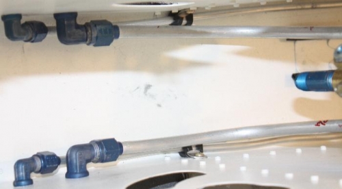
Step 5, Cut two 29-13/32” fuel lines from the ATO-035X3/8” aluminum tubing.
Step 6, Insert a AN818-6D nut and AN819-6D sleeve onto one end of the just cut fuel line and then flair one end.
Step 7, Add two snap bushings and a AN-931-6-16 Grommet as shown in figure 5. Attach the fuel line to the AN833-6D 90 degree Elbow on the 1048-L Fwd Fuselage Ribs and tighen to 100 inch pounds.
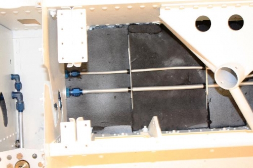
Step 8, Install the grommet and snap bushing into the 1084A System Brackets and locate the corresponding 1084B System Bracket Clips and the holding hardware, AN515-6R8 screw, AN960-6 washer, and AN365-632 nuts.
Step 9, I bent the excess fuel line 90 degrees aft approximately 1.75 inches from the Fuselage.
Time about 2 hours.
|
|
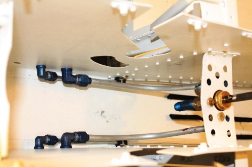
Bend the fuel line into a 90 degree angle
|
|
ATO-035X3/8” aluminum tubing
|
|
two 29-13/32” fuel lines from the ATO-035X3/8” aluminum tubing.
|
|
|
|
|
|
|
|
|
Copyright © 2001-2024 Matronics. All Rights Reserved.
|