
|

|
|
|
Conrads X-10 Build Log
|
Date: 4-19-2009
|
Number of Hours: 4.00
|
Manual Reference: Aileron 20-3
|
Brief Description: Section 21-3 Out-Board / In-Board Hinge Bracket an
|
|
4/18/2009 Section 21-3 Ailerons Steps 1 to 5 …. Step 1, Beginning with the Out-Board Hinge Bracket I clecoed the Main Rib, A-1005-L to the Spar Assembly A-1003-L and final drill the #40 holes to be counter-sunk as shown in Figure 1. Clecoed the Out-board Bracket, A-1006 also to the Spar Assembly and Match-Drilled #30 where shown. Step 2, Then using a 3/16 inch bit I final drilled through the Hinge Bracket, Doubler, Spar and Main Rib Spar Attachment Flange. Step 3, Then removed the Outboard Hinge Bracket and debured and counter-sunk the two # 40 holes. Repeated for the Right Aileron. Step 4, Moving on to the In-Board Hinge Bracket I repeated the process by clecoing the Main Rib, A-1005-R to the Spar Assembly, Final-Drilling #40 the four holes to be counter sunk as shown in Figure 2. Then clecoed the In-Board Hinge Bracket A-1007-L and Final-Drilled using a 3/16 inch drill through the two Bracket holes and into the Spar Doubler A-1008 and Main Rib A-1005-R. Then after testing the 3/16 inch holes with AN-3 bolts I removing the Bracket and Deburred and then counter-sunk the four #40 holes. Repeated the above for the Right Aileron. Step 5, Cut the A-710 Stiffeners from the provided angle strip aluminum as shown in Figure 3. There are 20 of these per Aileron so using the Sears Band saw with the aluminum cutting blade installed I marked and cut-out a total of 40 of these remembering to trim 13/32 inch out of each as shown in the figure. Total time about 4 hours.
|
|
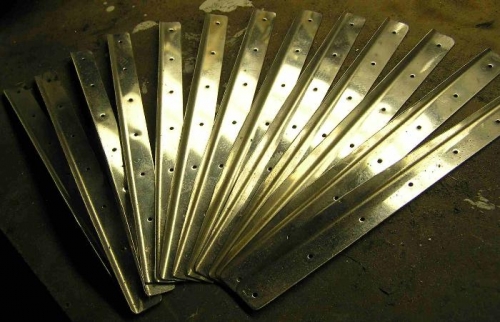
20 A-710 Aileron Stiffners
|
|
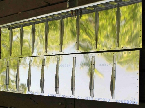
Aileron Stiffners in place
|
|
|
|
|
|
|
|
|
Copyright © 2001-2024 Matronics. All Rights Reserved.
|