
|

|
|
|
Conrads X-10 Build Log
|
Date: 9-23-2009
|
Number of Hours: 3.00
|
Manual Reference: 29-11 Steps 1 to 5
|
Brief Description: Section 29, FUSELAGE SIDE SKINS …. Pages 29-11, St
|
|
Section 29, FUSELAGE SIDE SKINS …. Pages 29-11, Steps 1 to 5
Step 1, Located the F-1069-R Forward Side Skin and the matching F-1069-L Forward Side Skin which a mirror the of the right skin and marked according to figure 1 and added the Bend/Roll line as explained.
Step 2, I added a cut angle to the Clamping Block that I previously used in creating the Mid Fuse Side Skin “roll”. At first I was going to removed 1 and 5/16” from the existing wood block as specified in the kit’s plan book but after further examination of the issue I am confident that the Clamping Block should work as is. I just beveled the edge of the wood block to R1/8 radius.
Step 3, I clamped the F-1069-R Forward Side Skin to the work bench and added the wood Clamping Block along the start of the roll line. In preparation for the 60 degree roll angle maneuver. Added the F-1070A/B Roll Construction Angle previously created to the edge of the F-1069-R Forward Side Skin secured the front with a #40 cleco. And ten clamped with C-clamps and Vice gripes as shown in figure 3.
Step 4, Began the Roll of the F-1069-R Forward Side Skin into a cone using the , I grasped the aft vice grip and rotated and pushed inward and down at the same time until I obtained approximately 60 degree bend angle specified in figure 4.
Step 5, I removed the single cleco from the forward area of the F-1070A and B Roll Construction Angles and grasped and rolled the forward AFT vice grip and then “banged” with a rubber mallet the skin to create a nice crease in the skin. This sound bad but in reality was quite easy once you set up everything according to the plans.
Time about 3 hours
|
|
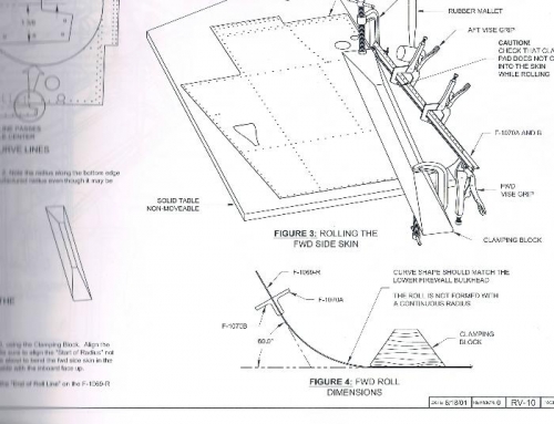
Figures 3 and 4
|
|
|
|
|
|
|
|
|
Copyright © 2001-2024 Matronics. All Rights Reserved.
|