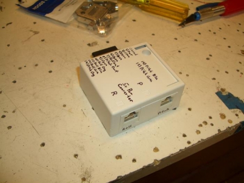
Today I made the junction box and power supply for the Trim indicators. The box has a 15pin D-Sub connector for power, servo signal, and EFIS connections. The other side has two RJ-45 ports to connect to the trim indicators. The indicator power is separate from the trim motor control. Of the indicators fail, it won't inpact the trim system. For now I just wrote the pinout on the box, I'll make a pretty label later.
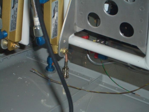
I also installed the trasponder antenna. I put is just inboard of the fuel vent on the pilot side. This meets the distance requirement from the X-ponder to antenna. The groundplane to the fron is a little short of the recommended 4", but from talking with other builders, that hasn't been a problem.
I may take some aluminum angle and match-drill it to the holes for the vent and antenna. Installed with one side of the angle facing aft, it will protect the connector in case I kick it with the size 13 boats.
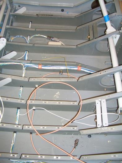
I rerouted the wire for the roll AP servo. I realized that I had it in the wrong bay of the floor for the standard installation. I hope I made the wires long enough....we'll see.