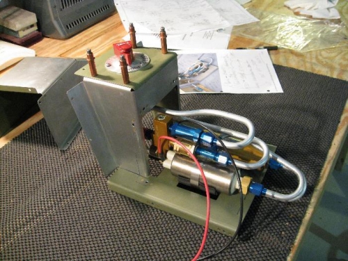
Brief Description: High pressure fuel injection pump
There is quite a bit of work in the high pressure fuel injection pump system, but it is required for all I/0 Lycoming type engines. The good news is that Van puts together a nice kit for easy fabrication. The work needs to be done meticulously, but there is nothing out of the normal. The case is either held together with rivets or held to the tunnel cover and fuel valve cover with platenuts. I recommend not following the dimensions on the drawing ahead of trial fit in the fuselage. There are plenty of opportunities for error due to the way it is held in place between the floor stringers. The tubing pieces take time and I managed to screw up one run before I got it right. Buy some extra 3/8’ aluminum tubing, because I would place a bet, that at least one of your tubes won’t turn out the way you want it. I also changed the platenuts in the fuel valve attachment to 8/32 since that is what all of the other attachment screws are. It doesn’t make any sense to me to have two 6/32 screws out of the fifty inside the fuselage to confuse things when I’m doing maintenance. I think this is a silly blunder the just wasn’t thought out by the designer or the drawing guy just made a mistake. I did prime inside the cover, but left the outside unpainted since I will be painting this with primer the is made for the grey Imeron paint I’ll be using for the inside of the cockpit.