Sort of a catch-22 situation. First step is to make the backshell assembly for the connector to the GEA 24, but, I need to at least approximate how the wires will route on the FWF side of things and penetrate the firewall, and then route internally past the fwd baggage compartment and into the avionics bay.
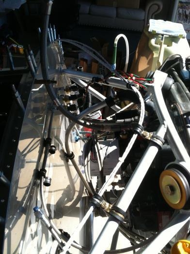
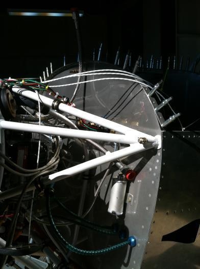
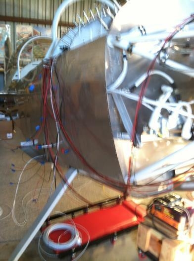
Decided to route the shielded wires using the same firewall penetration point as the main buss power. Made approximate cuts to wires and routed from avionics bay and through firewall, and routing using wedge clamps on the upper portion of the engine mount to get to the 3-port manifold for the Fuel Pressure, Oil Pressure and Manifold Pressure sensors.
Also routed in this bundle is the Oil Temp, RPM Pickup, and Fuel Flow (red cube).
I have not yet decided where the CHT and EGT sensor wires will route. These are not shielded, each is a two wire unshielded, essentially four wires per side.