
|

|
|
|
Buck's RV-8
|
Date: 9-22-2007
|
Number of Hours: 4.00
|
Manual Reference:
|
Brief Description: ELT and strobe-pack mount
|
|
I finished fabricating the ELT mount, including installing all the platenuts, installling the stiffener on the back of the plate, and drilling the attach-angles to the aircraft longerons. (Side note: I've noticed that people don't stop to chat when all they can see of you is your feet sticking out of the tail cone!) I also painted the mounting plate a nice industrial shade of gray.
Next, I began constructing the mounting plate for the strobe power pack, which will be installed on the right side of the fuselage, directly opposite the ELT. [Note: the stobe pack was later moved one bay forward.]
I cut and fabricated the mounting plate out of 0.040, and made a center, vertical stiffener, just like I did for the ELT. The top and bottom angles are the same, too, except I won't install platenuts on them. Instead, the power pack itself will be removable. I drilled and installed four 1/4" platenuts for the AN4-4A bolts that go through the mounting tabs on the unit. Because the strobe unit is pretty heavy, I drilled the platenut holes through another pair of stiffeners. I don't forsee any stress cracks on this thing, ever...
Once everything was drilled and clecoed together, I clamped the angles and mounting plate into the fuselage and began drilling them to the longerons. I'll finish this drilling tomorrow, then I'll prime and blind-rivet all the attach angles (ELT, too) into the fuselage with MSP-42 rivets.
|
|
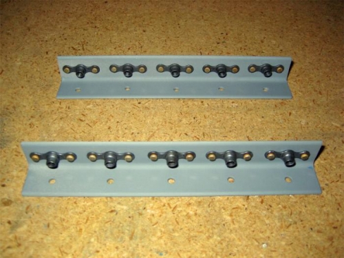
The ELT has five platenuts per attach angle.
|
|
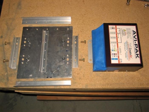
The major components of the mount for the strobe power-pack.
|
|
|
|
|
|
|
|
|
Copyright © 2001-2024 Matronics. All Rights Reserved.
|