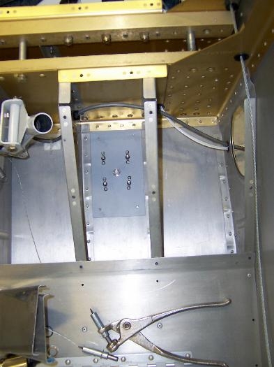
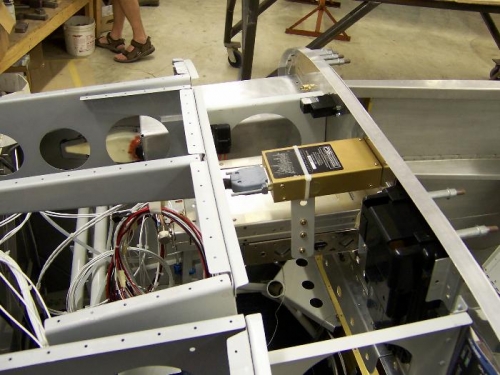
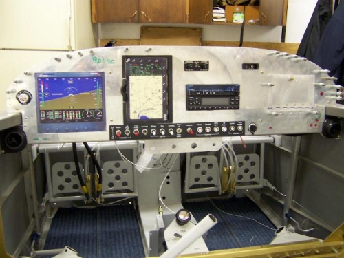
Repainted sub panel scuffed up from radio panel hole cutting. Painted intercom cable cover plate; now ready to install. Drilled ELT mounting holes and mounted ELT head with four black head screws. Plotted location for pilot and copilot headphone jacks, music in jack, and copilot push-to-talk buttons.Cut fuselage hole for transponder antenna behind pilots seat and mounted transponder antenna. Cut out ground plane plate for comm antenna. Drilled four mounting holes for comm antenna mounting screws. Cut fuselage hole and ground plane hole for comm antenna under co-pilots seat. Added plate nuts to allow antenna to be removed and primed ground plane. Mounted antenna to ground plane to test fit. Fit OK. Planned routing of antenna cables through main spar bulkheads then through center console and up to forward cabin overhead.Fabricated rudder cable linkages and installed to test for proper length. Fit OK. Painted cable linkages. Final install of cable linkages with bolts and cotter pins.Riveted map box hinges to map box and cover plate. Tested mating of cover plate to panel. OK. Clecoed in map box to panel and mounted panel to front sub panel. Screwed comm stack to sub panel mount and tie wrapped intercom to support. Made connection to intercom and mounted cable coverplate. All fits well.Installed platenuts to right wing tip for removable fasteners. Dimpled wings and countersunk wing tip for flat head screws. Mounted right wing tip to right wing to test fit. Fit OK.