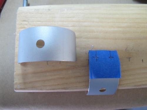
Pic. 1 There are 6 hinge-bolt reinforcing plates FL-005 with 4 holes each with a 1/4 inch edge distance all around. See pg 6-17. I made a tape template marked with the proper spacing and then hole punched the marked spot. I then transferred the tape to a new hinge plate and repeated the process. The center punched holes were drilled with a #29 and then clecoed.
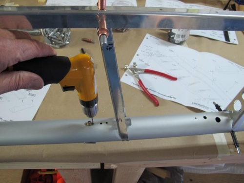
Pic. 2 With the frame secured I could remove the black clecos holding the front rib flanges, move the rib to one side and drill the nut plates with a #40.
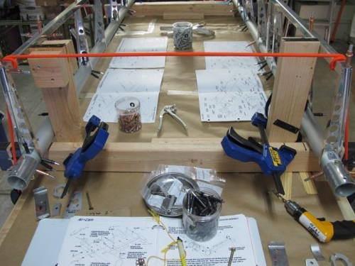
3. Securing the L and R sides of the EL made it easier to begin assembly of the spar roots on both pieces at the same time. This work is described on pg 6-18 revised 1/17/2012. I transfer drilled the 10 attachment holes in the spar root doubler EL=005 with a 19 x 30 step drill instead of using the #19 suggested by the Manual. Again, I think this improves accuracy and is easier to drill cleanly. I mark my drills with tape showing the size of the drill in the chock.
Note. The drawing on pg 6-18 showing the correct orientation of EL-023 is not a great depiction (in my view) of the way EL-023 actually looked in my Kit #195. Perhaps this piece has been modified and the drawing is still using a prior part. Either way I had to look at Glenn's site to see how it was done. Thanks Glenn! I still think the drawing can be improved.