Jake, Bob and John were present to construct and observe the Crank Case assembly. Today the crank shaft assembly was set into the right case half, aligning the dowel pin holes in each bearing to ensure proper seating of the crankshaft. Then the left case half was mated and the crank was rotated to check for any interference. There was no problem so the left half of the case was removed to continue the processes described in the manual.
Cam assembly lubricant was applied to each lifter and the cam shaft was set in place aligning the dot on the cam gear between the two dots on the crank gear.
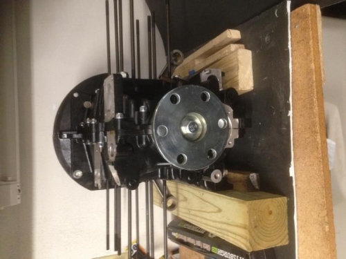
The flywheel was temporally installed so that the measurement for needed shims to fill the rear main bearing gap could be achieved. The measurement was accomplished by using a feeler gauge. The gap was 0.058 which was filled with two shims measuring 0.054. This was within the tolerance of 0.003 and 0.006 per the manual. The flywheel was then removed.
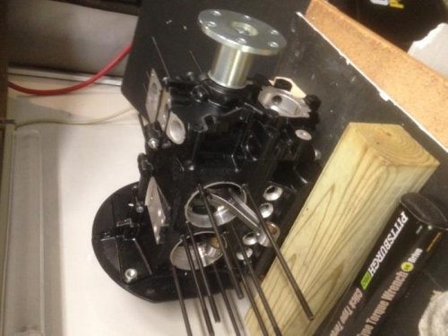
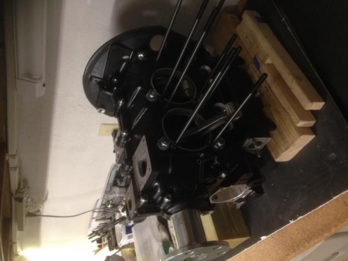
The Cam Plug was installed and Form-A-Gasket #3 was applied on it and all mating surfaces of the case halves. Then the two case halves were assembled. The six large elastic stop nuts were fastened to the six large studs and torqued per the manual instructions to 15 foot-pounds. The crankshaft was check for free movement. No problems were detected. Then the six nuts were re-torqued to 25 ft-lbs.
The remaining studs were fastened with washers and stop nuts as described in the manual. Had to go to Lowes and buy some bolts to use to hold tension for torqueing.
After the Fact Note based on later experience: 1. I wish I understood more about how the Oil Releif and Control Valves worked which maybe would have avoided an oil pressure and cooler issue which I had when starting on a cold day with thick cold oil. Reviewing the video after the fact I heard Joe Norris mention something about the possibility of an issue like I had. Neither the video nor the written instruction emphisize enough the need for the the plunger valves to be able to move freely in their ports. I sugges