Brief Description: Installing Interior Segment Of Fuel Vent Line
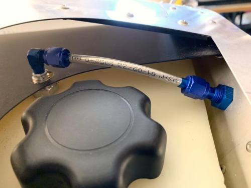
Installing the very short interior segment of the 1/4" OD aluminum fuel vent line. This run is only from the 90 degree elbow coming off the tank vent to the bulkhead fitting which ends with a 90 degree elbow on the firewall forward side.
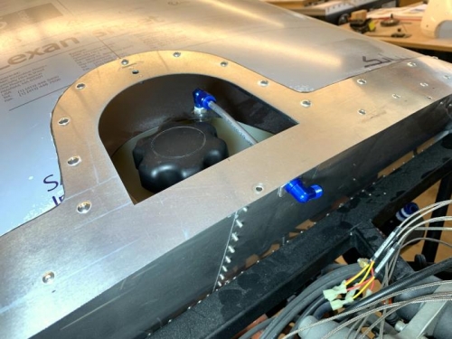
The first step was to install the 90 elbow on the tank fitting with teflon paste. My second step was to step-drill the hole for the bulkhead fitting. I had to produce a thick aluminum spacer to allow a single bulkhead nut to pull tight. The spacer was on the engine side of the firewall.
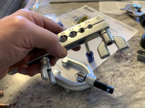
I had to get the feel for the doule-flare tubing flare tool, so I did a few practice pieces with soft copper tubing to check the length required and ensure I produce adequately flared tube ends.
Once comfortable with it, I cut the short section of 1/4" OD aluminum tubing, flared one end, installed both tube sleeves and nuts, then flared the remaining end. The short tubing section was installed, and all seems to be fine.
The remaining vent line run will be done on the engine side of the firewall. This method was approved by Kerry Forres before he retired from Sonex.
Installing a 37 degree double-flare on the 1/4" OD aliminum tubing.
Interior segment of 1/4" aluminum fuel vent line installed to and through the firewall.
Interior fule vent line installed through the firewall with a 90 degree elbow to direct remaining run.