Brief Description: Prop Hub Position - Short Of Spec - Part 2
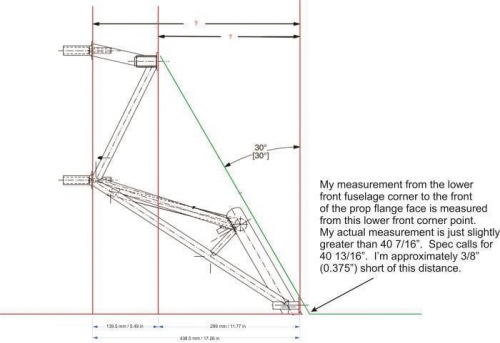
As for the hub position, I explained to Sonex Tech Support (Cris Nash) that my prop hub face was only reaching to 40 7/16", ~3/8" short of the specified 40 13/16" distance from the front lower corner of the fuselage. Cris sent me a diagram of the engine mount, asking for measurements of two key mount distances. I made the measurements (see attached diagram for measurement and angle verification results), and Cris verified that the mount measurements were spot-on. This verified the mount was not out of manufacturing specs.
We then decided to install all four Jabiru provided 3mm spacer washers to the aft side of the rubber shock mounts to move the engine slightly forward. I added enough additional AN-365 washers to the current AN5-50A bolts that the proper torque could be achieved. Upon doing this, I found the engine block upper flat surface was just slightly less than 0.5 degrees nose down from parallel of the extended fuselage bottom line. I then removed the two upper 3mm spacer washers and reinstalled the engine to proper torque. This time the engine was less than 0.25 degrees nose down of parallel to the extended fuselage bottom line. I remeasured the distance to the face of the prop hub, and it was now at 40 9/16”. It was now only ¼” short of the spec, and Cris felt that was the best that could be achieved, as Jabiru only allows a maximum of 3mm of spacer to be applied to each mounting pin. The biggest concern with this shorter distance to the prop hub face was additional material removal from the back edge of the cowling pieces and the achievable cowl fit.
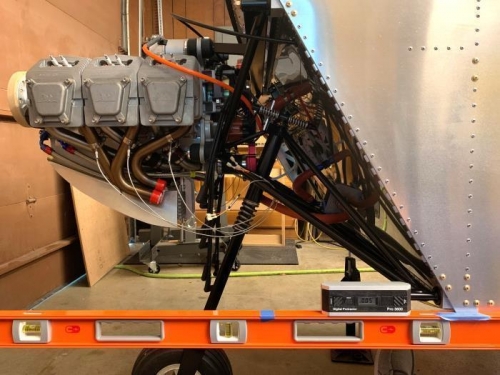
Using a 6 foot cabinet level to extend a fuselage bottom line out from the plane bottom.
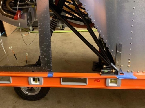
Using right angle squares to measure points along the extended fuselage bottom line.
Final measurement results for the engine mount key position points and angles.