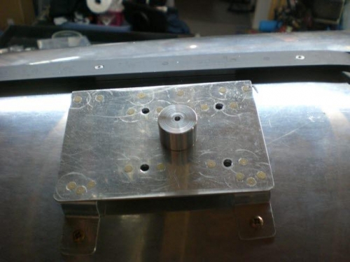
I began by riveting the two nutplates to the doubler for the outboard attachment feet for the mount, I screwed down the feet to the fuselage and checked the mount over.....very secure and great fit.
I went into the shop and made a drill jig to drill the hole for the connector perpendicular to the mount. One of the challanges of designing and building the mount has been the curve of the turtledeck as well as the angle of the turtledeck as it goes rearward. That is one of the reasons I chose an angle for the base mount inboard.....and a couple feet for the outboard because they are easier to adjust and keep everything level....I simply adjusted the bends in the feet to accomodate the curve and angle problem.
By making a simple drill jig I could assure the hole in the fuselage for the connector would be in alignment and perpendicular to the GPS mount. I used a #30 drill to make the pilot hole and then a step drill to make it .625 diameter.
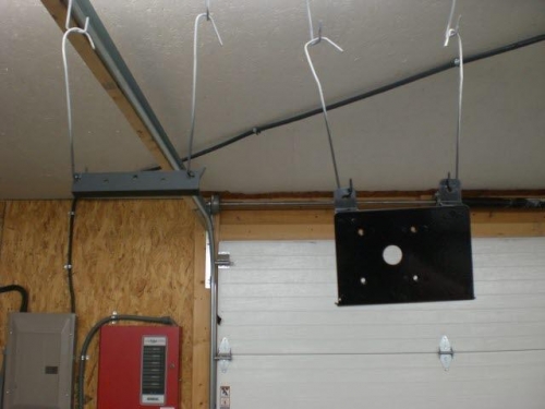
I primed all the parts and then topcoated them with flat black enamel which I felt would be least visible and neutral enough to go with the eventual paint job.
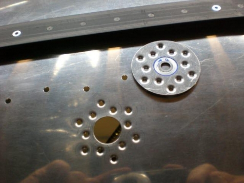
Finally I placed the connector hole doubler in place and drilled the holes through the fuselage and dimpled the fuselage skin and dimpled the skin and doubler. I wasn't even sure there needed to be a doubler since that hole is only a clearance hole for the connector...but I felt it needed the extra strength in the area for good measure.