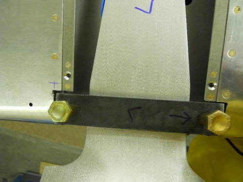
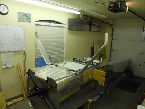
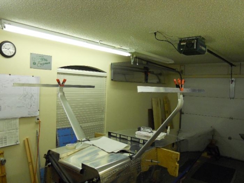
Trimmed right skin for fit of the outboard mounting bracket. In order to get enough clearance, I had to trim the skin on the aft side and eliminate a rivet. I may add another rivet back later—maybe a NAS (countersink the skin) or just use a pop rivet. Either will be hidden under the fairing at the top of the gear leg. Went back to the left side and cut out the rivet also. Both brackets fit much better now. Bolted on the gear with a 7/16" bolt thru the gear weldment, inboard wear plate and bracket. Picked up an 8’ aluminum angle 1.5” x 1.5” from Lowes Aviation Department. Cut the angle in half. Clamped the two piece together and trued up the cut end on the band sander. Measured the 2 pieces and have exactly 4’ each. Next I marked a line on each angle at 2’. The Grove gear is slightly rounded on the tip of the gear, so it is not possible to align the angle with a flat end such as on the standard gear. I found the center of the wheel attach point and extended the line to the end of the gear. Used this line to match up with the 2’ line on the angles and clamped into position. Moved the angles around until they were level. Probably will either drill the angle and bolt to the gear leg or use some C clamps to secure them. Next up—lots and lots of measuring –this alignment thing has got to be exact or pretty darn close to exact.