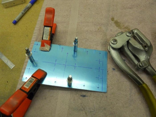
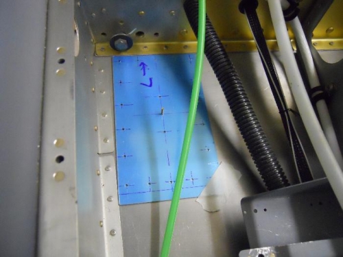
Started on mounting comm. antennas tonight. I cut some .032 sheet stock so that I had two plates the same size to fab the doublers for the antennas. Laid out rivet holes on the left plate as well as the antenna mounting holes and the hole for the cable connection. Center punched the holes, then clamped the two plates together and used a Whitney Jr. to punch 3/32” holes thru both plates. I drilled the two mounting holes and the hole for the coax to 1/16” (thru both plates at same time). I taped the doublers in position to check for clearance with the aileron push/pull tubes and also the rear seat footwells. In looking down at the doublers, I observed that the 2 mounting holes did not appear an equal distance from the center coax hole. Removed the plates and measured again—looks like I was a little off on the measurement. Took a piece of scarp .032 and very carefully laid out the holes again. Center punched and drilled the holes to #41. Clamped this scrap to some angle stock and match drilled these holes. If these holes are properly spaced, I wanted the angle stock for a template. I drilled the 2 mounting holes in the scrap to #19 and used a unibit to open the center hole to 9/16”. Checked the fit with the comm. antenna and it was perfect. I clamped the angle to the 2 doublers and match drilled the mounting holes and coax hole to #41. Next up is drilling the doublers to the fuse floor skin.