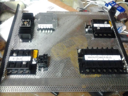
Current layout of the power bus tray. On the top right is the always-hot battery bus fuse holder. 8 slots should be plenty. As of this writing, I can only think of 2 items that require constant power even when the master is off. The little box next to the fuse holder is the over-voltage protection module by Perihelion design. I'm told that this is slightly more elegant than the Nuckoll's 'crowbar' module, and I know of several builders who've swithched to this unit. Lower right is the main power bus, with the potential for 14 fused circuits. Moving to lower left, I have the 8-circuit essential power bus, which will power all the avionics equipment, as well as the relay that provides an alternate power feed to the e-bus only, to instantly minimize the power-draw in case of an alternator loss. Upper left shows the Schottky diode and heat-sink (Nuckoll's concept) that prevents back feeding into the main bus (if I use the alt e-bus feed scenario above). The grey device is the John-Deere voltage regulator for the 20 A dynamo.
These items can be moved around if needed, but right now they are placed to accommodate wire 'streets' that will run between devices, and then all flow to the back of the tray where it connects to the firewall.