
|

|
|
|
Rob's REBVAIR Project
|
Date: 10-10-2010
|
Number of Hours: 20.00
|
Manual Reference:
|
Brief Description: Rudder cable exit holes (part 1)
|
|
As any Rebel builder will tell you, locating and drilling the rudder cable exit holes is one of the more nerve-wracking tasks one faces. The whole procedure takes about 2 lines of text in the manual, but entire dissertations have been written to describe the planning required to avoid an end result like Image 1. Clearly, I hadn't planned it out properly, and as the hole got larger, my nibbling got more aggressive....mostly out of frustration. In the back of my mind I had told myself that my doubler would just have to be a bit bigger than most. But once I stepped back from Image 1, I saw there was no alternative but to remove the offending FUS29 altogether. Once again, I thanked my lucky stars I was building a metal airplane!
Since I had also redone the upper FUS29 about this time last year, I knew it wouldn't take long to fabricate a replacement. This became an opportunity to go to 0.025" (from 0.020") material, which would also help improve the connection with the oval FUS36 bulkhead you see in Image 2. There were a few rivets at that connection that had not set themsleves correctly due to some misallignment between FUS30, FUS29, and the bulkhead. I had circled these as needing to be replaced one day when I had my head stuck in the tailcone for some other reason. Well, removal of FUS29 made this task that much easier. As a final bonus, the old FUS29 drilled edge could be salvaged as a 0.020" spacer strip to tighten up that area as well.
So once I had my new lower FUS29, I used the grotesque, yet informative hole in Image 1 to guide the placement of the new hole, and you can see the results in part 2...
|
|
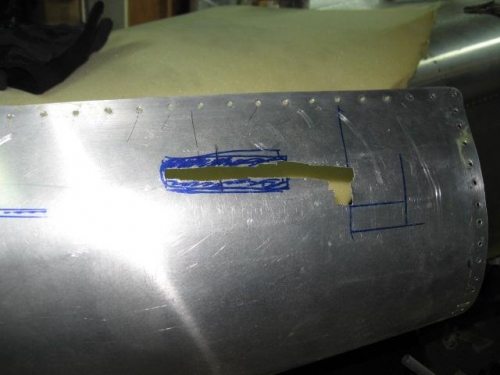
a little to aggressive with the nibbler
|
|
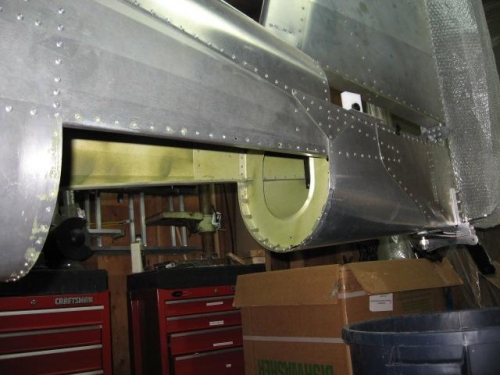
oh well...I'll just have to replace it
|
|
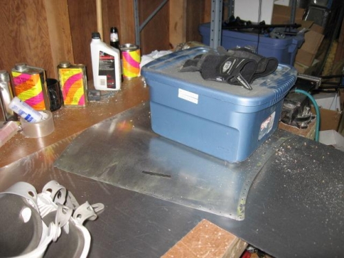
use the old to make the new
|
|
|
|
|
|
|
|
|
Copyright © 2001-2024 Matronics. All Rights Reserved.
|