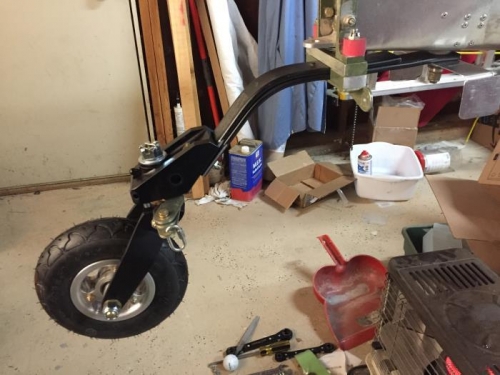
Took a bit of a hiatus in December, and 2020 begins again with lots of little items. Here I've installed the Matco tailwheel on the modified Aeronca tailspring. This took longer because I decided to swap out this previosuly installed aeronca spring for the MAM aluminum 'slab'. Why? Because I thought I recalled someone on the builder's list saying they were using stock spring and tailwheel with no issues. Asking that question again on the forum, several said it was too stiff, even with a pneumatic tailwheel like mine. So I put the aeronca spring back in again.
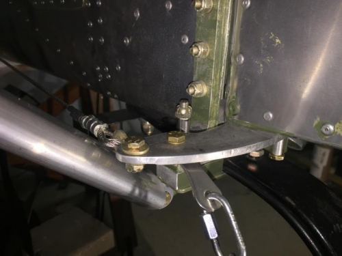
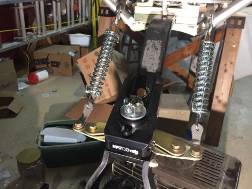
In image 2, I've installed the spring and chains that connect the tailwheel arms with the rudder arm. Here, one needs to pay attention to the clearance between the new MAM Horizontal Stabilizer (HS) strut and the rudder control arm through its range of travel. It's not more than 1/8" if you use an the prescribed pint. Looking into the shadows beyond the control horn, you can just make out a 0.040 bracket I've fabricated and attached to the tail wheel attach bolt. That's a hard point for a future tailwheel fairing.
The tailweel is set at the factory to un-lock at 35 degrees. The locking angle is controlled by the interference between a set of pins and the control 'wings' or 'arms' on the wheel. The rudder travel is 25 degrees, and if I can't get it to release during taxi testing I'm going to have to add (weld) on a bit of steel (only about 1/16") to the 'wings' to .