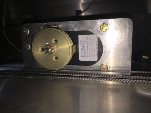
You can see it all coming together in these images. Image 1 shows the servo (and the capstan cage) having adequate clearance between all the moving components. The lowest point of the cage sits about 1/8" above the control cable. The 1/16" bridle cable then clears the control cable by about 1/8".
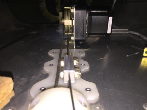
In image 2 one can see how the capstan is centered over the control cable, and the alignment of the bridle and control cables is good.
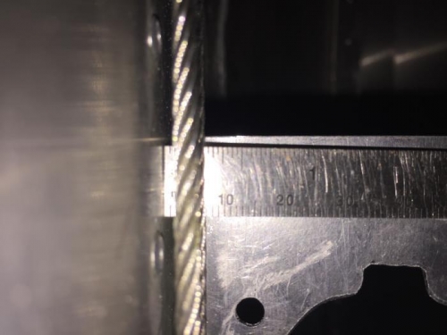
Image 3 was an attempt to show the clearance between the control cable and the floor. As noted earlier (and supported by Part 4 of this series), builders just completing this area of the aircraft may want seriously consider adjusting the construction here to beef up a capstan servo installation. I think everything worked out just within limits for me. Up next....termination of the cable ends and final adjustments.