
|

|
|
|
Rob's REBVAIR Project
|
Date: 2-21-2015
|
Number of Hours: 3.00
|
Manual Reference:
|
Brief Description: Panel Wiring Part 10: wig-wag circuit
|
|
In Part 8, I described my wig-wag light set-up. In this installment, I detail the final soldering of the simple Schottky diode array needed for the system. Why are these necessary? Well, they are there to electrically 'limit' the current flow through either the continuous, or wig-wag circuits. They are the electrical equivalent of a one-way valve. Without them, both circuits would be open, and neither would work correctly.
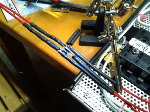
I'm quite certain I'm not the first to wire up two lights this way; there's just no other way to do it if you want to use the same lights for both continuous and wig-wag circuits. Further, using the diodes close to the power source allows a single power/ground pair for each light (Image 1, 2 red wires in the upper left hand corner).
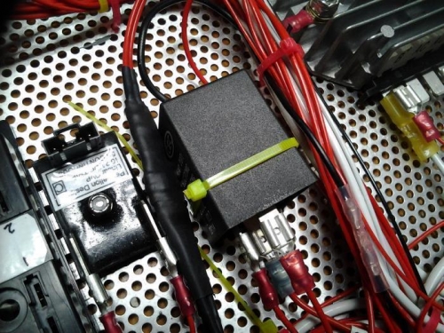
Carefully applied layers of heatshrink complete the fabrication (Image 2) and the assembly will lie flat next to the flasher unit in the tray.
In Image 1, the three wires coming up from the bottom right are (from left to right), left lamp power (from flasher unit), continuous power (from 'continuous position on the toggle switch), and right lamp power (flom flasher unit). The center power wire is then 'forked' into two diodes, and the downstream leads are connected to the right and left lamps. The two left and right power wires also pass through their respective diodes, and join up the first, forked diode pair (see Schematic).
This project is easy to source, and easy to fabricate. I'm thrilled at how comparatively inexpensive this was, and how it worked the first time through.
|
|
|
|
|
|

|
|
|
|
|
|
|
|
|
Copyright © 2001-2024 Matronics. All Rights Reserved.
|