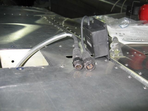
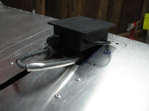
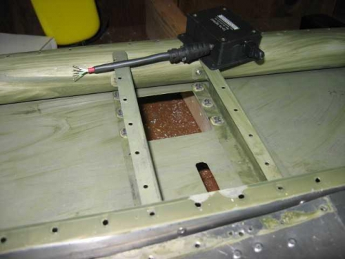
Here's the Switchcraft connectors all buttoned up (Image 1). (Mouser electronics part numbers 502-EN3L5F and 502-EN3C5M). Soldering was a snap with a nice hot Weber soldering iron, the right 37:63 solder, and techniques from aeroelectric.com. Has me seriously considering soldering all my connections instead of crimping when I get to the panel. We'll see. Image 2 shows how the cable will be routed within the confines of the two ribs, along with the polyurthane tubing for abrasion resistance. The loop is fairly long due to the sheer length of the two connectors. Image 3 shows the interior of that same area, with 6 Clickbond-brand nutplates installed to receive 6-32 stainless screws. Keep the wires exiting the servo bent when you heat the heat-shrink tubing and it will retain the bend nicely. If I had to do this again, I'd either separate the ribs by another inch, or use right-angle connectors (or one bulkhead connector) instead of these in-line models). Nevertheless, relatively straightforward (if you stand on the shoulders of others)...:)