
|

|
|
|
Rob's REBVAIR Project
|
Date: 10-15-2010
|
Number of Hours: 10.00
|
Manual Reference:
|
Brief Description: Rudder Cable exit holes (part 2)
|
|
Standing on the shoulders of giants, I ended up with a 0.5" wide x 3.5" long hole in just the right spot in my new FUS20 (Image 1). Here you can also see the custom fabricated nylon fairlead, as pioneered by several builders before me. Due to the width of the actual fairing opening (Image 3) the four rivets you see in Image 1 are countersunk. Only two of these are used to attach the fairlead itself.
Image 2 shows the relative location of the exit hole in my Rebel, in case someone wants to try and duplicate this. However, as I found out (painfully), the location of the hole in the skin is wholly dependent on the position of the fairlead just forward in bulkhead D (or is it E?). Although not shown here (see rudder cable install), I had my rudder cable go through the bulkhead, instead of around it. This was to try to keep the entire cable run as straight as possible. I'm fairly happy with the resulting angles.
Finally, the fairing in Image 3 was modeled after fabrication techniques found throughout the web. The photo does not show the dozen or so attempts at getting the correct cosmetics and/or size. This was simply "good enough", and the other side (not shown) looks about the same. Yes, I did try to make use of the ACS fairings for $12.95, but to my dismay, I found myself trying to make the hole fit the fairing size, rather than the other way around. Maybe there's a kit plane out there that can make use of those fairings, but they look to me like they were intended for RC aircraft.
|
|
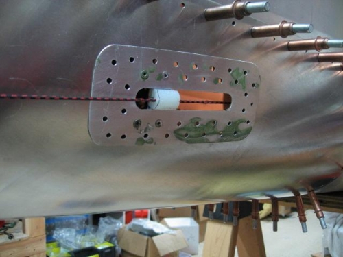
fairlead and doubler in place
|
|
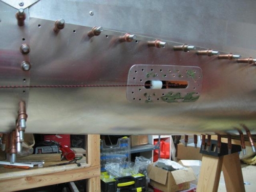
relative location of hole to fuselage
|
|
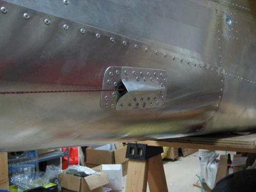
final product
|
|
|
|
|
|
|
|
|
Copyright © 2001-2024 Matronics. All Rights Reserved.
|