
|

|
|
|
Rob's REBVAIR Project
|
Date: 3-13-2010
|
Number of Hours: 10.00
|
Manual Reference: Chapter 20
|
Brief Description: Mixer arm et al.
|
|
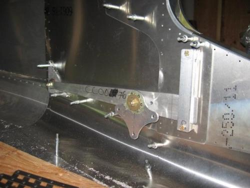
This is a photo you'll see in a lot of Rebel builders' pages: it's known as the mixer (CC-48-2) and the arm on which it pivots. This mechanism is responsible for the 'flaperon' feature of this aircraft. Like a lot of things on we do on this aircraft, it look simple enough, but there are a number of things to consider as one installs this mechanism.
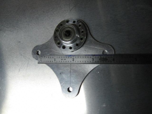
Firstly, the mixer itself is asymmetrical, and my 2006 edition of the manual does not specifically refer to the asymmetry, nor accurately describe its installation. A MAM rep (Jeff), as well as archives on the builders' list, provided the necessary details. In the shot you can just barely see a centerline drawn between the lower bolt hole, and the bearing above it. From this centerline, the distance from the bolt hole in one arm is longer than the other; this one points forward. This impacts how you install the bearing insert, because the bearing insert should sit between the pivoting arm and CC-48-2. Why? you ask. Because the 1" push rod that will install to the lower bolt hole (not yet installed in image 1) will need to clear the vertical retaining structure you see installed to the side of the fuselage (just ahead of the mixer). The arm slides up and down inside this retainer, so when the mixer arm is at its highest detent (18deg flaps), full left or right aileron deflection will bring the aforementioned control tube in very close proximity to the mixer arm retainer. Thus, the mixer itself should sit as far away from the entire assembly as possible, which brings us back to the bearing placement.
The next item of interest is the 1/4" hole in the mixer arm (just ahead of the mixer itself). This is where the teleflex cable will attach with a clevis. In my case, the clearance between the 1/8" fuselage doubler (retainer mentioned above is bolted through this doubler) and the mixer arm could not accomodate this clevis and its pin. Thus I needed to position the arm itself so the 1/4" hole was positioned just aft of the 1/8" doubler, which provided an extr
|
|
|
|
|
|
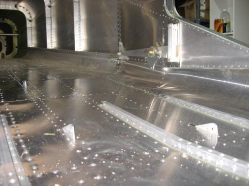
final install
|
|
|
|
|
|
|
|
|
Copyright © 2001-2024 Matronics. All Rights Reserved.
|