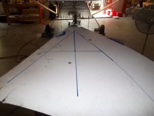
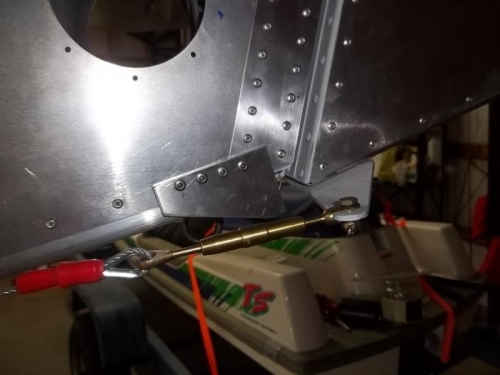
To set the rudder stops, I pretty much used the HBH method of determining deflection. I took a piece of scrap material (formica laminate in my case) and drew a centerline and lines 20 degrees either side. Taped some scrap piano hinge to the rudder trailing edge and let the rudder hinge pin hang down. Drilled a hole at the vertex and put the protruding hinge pin into the hole. Set the scrap piece on a box a bit below the fuselage. Visually aligned the trailing hinge pin, rudder hinge pin, and my ELT antenna which is mounted on the fuselage centerline. This gave me the proper scrap alignment for rudder centered. With the alignment scrap taped in place, I could calibrate the stops by moving the rudder until the trailing hinge pin points to the proper 20 degree line. With a combination of clamps and tape, I was able to position the stops. I was able to use a long #30 drill bit to drill out the passenger side using the holes in the pilot side. Unfortunately I had already expanded the pilot side to final size when I assembled the fuselage, so I had to get creative since I didn't have a long #20 drill bit. I was able to put a piece of tape on the insede of the stop and hand twist a bit from inside to mark the tape for drilling. Got everything prepped and riveted with AS5. Then reattached the rudder cables and put cotter pins in place.
Also added the mounting bolt hardware for the Hstab.