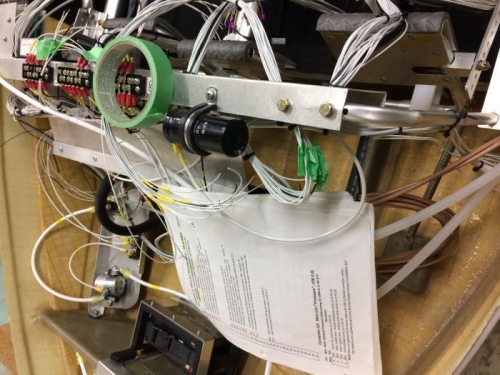
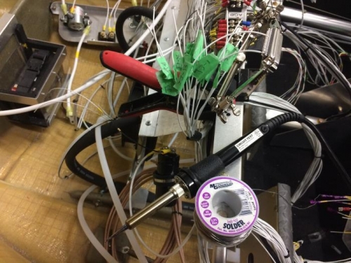
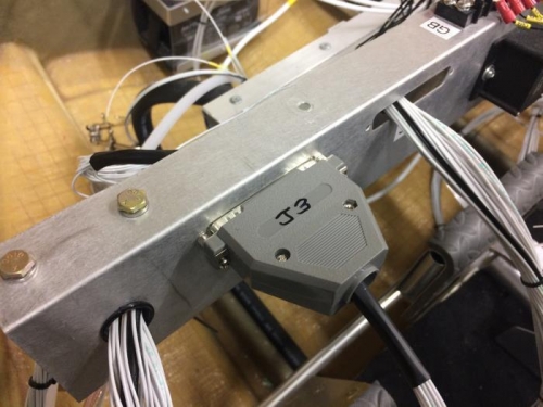
After working in Chile for seven months I am back on my 'real job': building "The Spirit of Mackenzie". With the help of Elayne, who I met in Chile, and spread over four days we figured out how the wiring of the ACI SeaRey Harness works in the area of the Harness Support Tray and the switches, lights, gauges, EMS, EFIS and other terminating points mounted on the Flight Deck and the Centre Console and started installing. Most, but not all, of the wires in the Harness route through the Support Tray via D-Sub connectors using soldered pins. J1 and J2 D-Subs are for the Skyview and are already complete and ready to plug in to those Avionics. J3 is for the Warning Lights in the Pilot's panel; J4 is for the Communication Avionics in the Centre panel; J5 is for the Co-pilot's panel; J6 comes already complete for plugging into the Gear Alert module; J7 is for the Switches in the Centre panel; J8 & J9 are for network cables and J10 is for a Firmaware USB socket. In these four days we cut the individual wires for J3 and J5, soldered them to the appropriate pins and mounted the D-Subs into the Support Tray. My everyday handyman soldering gun was too big for soldering these small pin connections so I bought the 'professional' soldering iron shown in the second photo below. The grey plastic caps shown in the third photo didn't come with the Harness so had to be purchased from an electronics shop.