
|

|
|
|
Miguel Vidal RV-8
|
Date: 12-17-2021
|
Number of Hours: 3.70
|
Manual Reference: 8s8PP-1r1 8-18
|
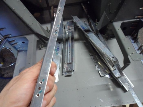
Brief Description: Mid Fuselage Skins and Structure
|
|
From Construction Manual steps:
Separate the F-805B-L-1 & -R-1 Floor Support Angles from each other (See “F-805B-1 Floor Support Angle Detail”, DWG 69). Deburr the edges of the Floor Support Angles.
Deburr the edges of F-860A-L-1 & -R-1 Fwd Arm Rest, F-860B-L-1 & -R-1 Middle Arm Rest, and F-860C-L-1 & -R-1 Aft Arm Rest (See “Left and Right Arm Rest Rivets”, DWG 69).
Deburr the edges of the F-805-L-1 & -R-1 Fuselage Bulkheads and the F-806A-L-1 & -R-1 Fuselage Bulkheads (See “Mid Fuse Side Skin and Structure”, DWG 69). Enlarge the 1/8 pilot hole at the top of each bulkhead for a snap-bushing to allow routing the static line and wiring.
Deburr the edges of the two F-805G-1 Gussets, and the F-815C-L-1 & -R-1 Outboard Seat Rib Angles (See “Detail B”, DWG 69).
Final-Drill # 40, the nutplate attachment rivet holes in all parts from the four previous steps.
Machine Countersink the nutplate attachment rivet holes in the F-815C-L-1 & -R-1 Outboard Seat Rib Angles, and the F-806-L-1 & -R-1 Fuselage Bulkheads for flush rivets.
Deburr, then dimple countersink, the nutplate attachment rivet holes in the F-860B-L-1 Mid Arm Rest, and the F-860C-L-1 & -R-1 Aft Arm Rests.
|
|
Machine countersinkin nutplate attachment rivet holes in the Arm Rest pieces.
|
|
|
|
|
|
|
|
|
Copyright © 2001-2024 Matronics. All Rights Reserved.
|