Brief Description: Main Gear Leg Fairing Installation
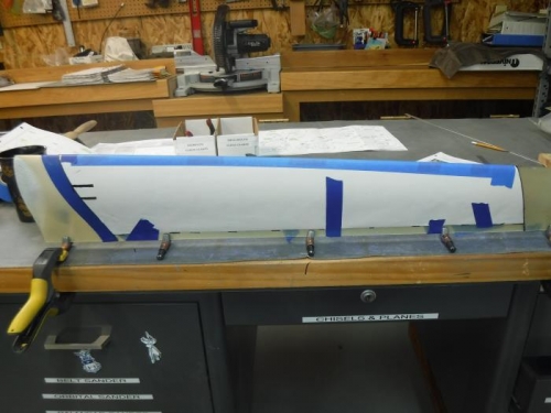
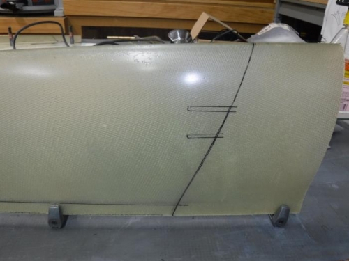
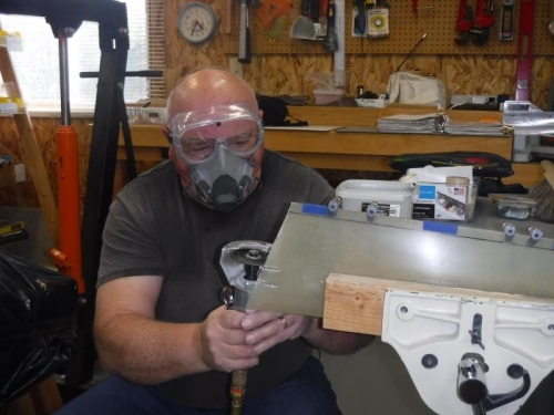
Installing the wheel and gear leg fairings add about 12 mph to the top speed of the aircraft which equates to approximately 27 horsepower. However; they have to be installed in the landing gear flight configuration (airplane wheels off the ground) so I had to lift the RV up onto sawhorses. There is more messing around with these fairings than I expected. VAN’s provides a cutout template for the main gear leg fairings in Drawing C3 to cut the fairings to length and to create notches for a hose clamp which holds the fairing. After the cut outs are made, I riveted a piano hinge onto the inside of the leg fairing trailing edge. The instructions don’t designate how far forward from the trailing edge the hinge is supposed to go, but I inset mine about ¼” forward so the fairing edge trailing edges would be solidly pinched together when the hinge pin is installed. This will make installing the hinge pin from the bottom difficult but it should hold the fairings onto the gear leg securely. In the drilling, clecoing, de-burring, countersinking, and riveting process; you have to make sure the fairing doesn’t twist and you also have to use soft rivets which you don’t fully set. I ended up using AN426AD4 versus smaller AD3 rivets because my countersunk holes in the fiberglass unexpectedly expanded and the designated rivet size didn’t fit. The pictures below show the cutting and riveting process.