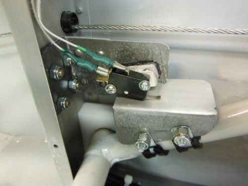
It took me most of the day yesterday experimenting with different "home-made" mountings for a flap switch to trigger the AOA computer. I finally decided on mounting the switch on the right flap extension arm and wiring the switch in the NC lug configuration (see below).
For flap/slat settings in between cruise and landing configurations, the AOA Instrument's flap switch must be set up so that the AOA CPU is using the most conservative database to compute AOA. This is usually the flap down database. When the ports are located outboard of the flaps, the flap down switch should electrically ground the AOA "FLAP" wire by 1/3 flaps and remain grounded through full flaps. In some installations like RVs the instructions say it may be easiest to activate the arm of the micro switch as the flaps move into the up position. In this case the AOA "FLAP" wire would be connected to the micro switch NC (normally closed) lug.
I have major heartburn with Advanced Systems lack of instructions, diagrams, or pictures on how to install a flap switch on an RV (or any other airplane). They basically said build it and don't screw it up or the indicator won't work properly. Also the lugs on the switch don't fit standard connectors. I nearly broke the switch trying to get standard connectors to fit and ensure I would have a good electrical connection considering all the vibration related to normal flying. Just to be sure I epoxied the connections after crimping, leaving enough extra wire in case I ever have to change the switch.