BIG TIME CORRECTION TO THIS PAGE (updated 6/18/14)
See the engine post on 6/7/2014. The magnet was NOT reversed. I misread the instructions on determining the magnet polarity and reversed it when I did not need to !!! Do not screw up this test like I did !!!
1. Bought longer stainless steel (metric) bolts for the valve covers (since the Sonex-supplied ones were too short to work), so got the covers installed.
2. Installed the rest of the prop flange lugs (see yesterday's post).
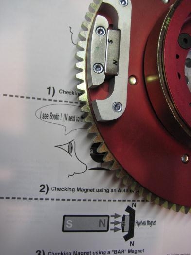
3. Per the manual, you need to check the magnet on the flywheel to ensure the face that is facing OUT away from the flywheel center, is the SOUTH pole of the magnet. Guess what? MINE WAS FACING IN THE WRONG DIRECTION! That means my primary ignition would NOT have worked properly if I had not fixed it.
The magnet is the bright shiny rectangle BETWEEN the two oddly shaped pieces; it's not the odd shaped pieces themselves. In photo 1 you can see the N and S of the magnet that I wrote on there. This was AFTER I determined which was N and S. The poles are along the LONG edges of the magnet; not the short ends.
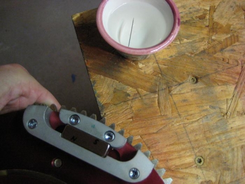
I had no compass or anything else to check N/S, so I did a McGuiver. In photo 2 you can see a sewing needle floating in some water. It floats there by surface tension. Before I put it in the water I magnetized it by scraping it on a refrigerator magnet. I know which way my house faces I noted that the eye-end of the needle faced north.
In photo 2 I have the magnet on the flywheel, but to do the test I actualy removed the magnet, but it actually works either way. In that photo you can see the North end of the needle being pulled toward the South end of the magnet. But when I first did the test the magnet pushed the needle away and spun it around 180 degrees, proving my magnet was facing the wrong way!
With the magnet turned around a
The little illustration at the bottom is trying to represent the magnet assembly on the flywheel.
Using a needle/water compas to check the flywheel magnet