
|

|
|
|
Michael Heit Excalibur Build
|
Date: 11-7-2005
|
Number of Hours: 1.50
|
Manual Reference: AC 43.13
|
Brief Description: Part Five Wiring of Instrument Panel
|
|
Photo 1: Shows the finished connectors prior to being placed on the starter switch. All crimps have been made with the proper tool setting, and a solder joint made such that the solder flows smoothly into the body of the crimp, but not so much that it will wick up into the wire bundle beyond the crimp. If you let the solder wick up into the strands of the bundle past the crimp, it will become ridged, and break from vibration over time. By tinning the leads, and allowing the solder to just start to flow into the crimp from the exposed cut end of the wire near the center of the connector, you can prevent the solder from wicking into the strands in the bundle. A slight side ways movement of the wire at the outer end of the crimp after you complete the solder job will tell you if the solder has wicked into the strands beyond the crimp area.Photo 2: I needed to join the wires of the RPM gage to those corresponding the same color in my wire bundle, so I took this photo of the ends being mated with a good physical connection prior to being soldered. Note the shrink tubing to the left of the connection, it is black. This will be drawn over the connection after the solder is done, and will insulate the wire from the remaining connections in the bundle. I'll show photos of the shrinking process in the next set of this series.As for the mechanical connection, after this photo was taken I crimped down those loops you see in the photo. I wanted to show the loop process of how important it is to make a good connection before solder is applied.Photo 3: A good solid solder joint. The solder is smooth, there are no sharp edges protruding from the wires being connected, and though this is not the best photo, the solder should be shiney, if it is a dull or foggy color, the solder joint has crystallized, and needs to be resoldered. Usually this is cause by movement in the joint before the solder has had a chance to cool properly.
|
|
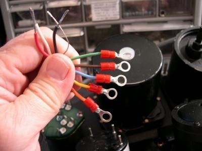
The completed starter switch harness
|
|
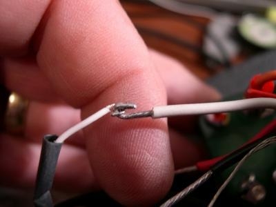
Making a good mechanical connection
|
|
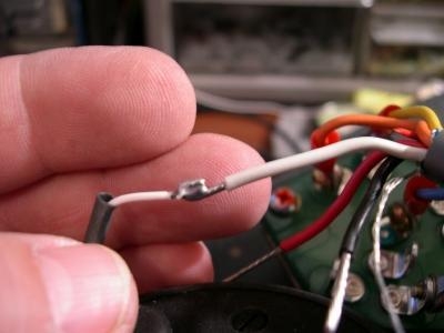
Solid solder joint
|
|
|
|
|
|
|
|
|
Copyright © 2001-2024 Matronics. All Rights Reserved.
|