
|

|
|
|
Michael Heit Excalibur Build
|
Date: 9-30-2008
|
Number of Hours: 5.00
|
Manual Reference: Builders Manual
|
Brief Description: Building wings part 5
|
|
This days work session was a long one as I read, and then re- read, the builders manual. I am rewriting the manual hopefully into a more concise, clear methodology of how to assemble the aircraft. That being the case each step has been carefully thought out, and documented, for future use in the new manual.
The first step is to determine which side is the top of the wing. It is possible to get the bottom of the wing up and risk the potential mistake of drilling on the wrong side. The trick is to locate the wing lift strut holes, and see how the angle of the holes for the rear spar lift attchment holes are drilled at an angle, so as to bring the attach brackets downward, and inward at an angle towards the center of the wing. The front spar lift strut bracket attach holes are drilled so as to bring the lift strut brackets stright down from the front spar tube.
Be certain you have made the effort to get the proper wing layout, and that the bottom of the wing is facing down on the table. Take an aluminum tube from your kit, and with one person on one side of the wing, and you on the opposite side, run the tube down the length of the spars and mark the top of the spars by gently putting pressure on the spars as you run the tube down the length of the spars. Be sure to walk slowly and at an even pace.
Photo one shows the mark left by the aluminum tube rubbing into the top of the alclad layer of the spar tubes.
Next, as shown in photo two, from the ROOT END of the spar measure and mark 1.250" using a Sanford Ultra Sharpie marking pen.
The first rib will be aligned with the inside edge of this line made in the previous step. The rest of the layout is done in similar manner, even the dimensions of the aluminum plate that will eventually be placed on the top and bottom of the wing root area. The placement of the first two ribs is critical to get the proper location of the rest of the ribs.
Photo three shows the markings for the rest of the layout prior to any drilling.
|
|
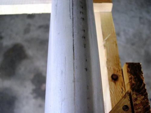
Top of spars marked for center
|
|
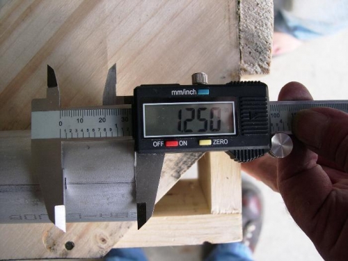
marking dimension of first rib location
|
|
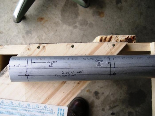
Dimensions marked on spars
|
|
|
|
|
|
|
|
|
Copyright © 2001-2024 Matronics. All Rights Reserved.
|