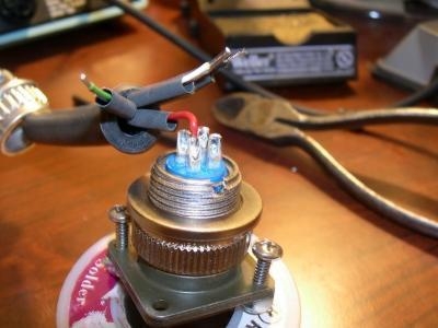
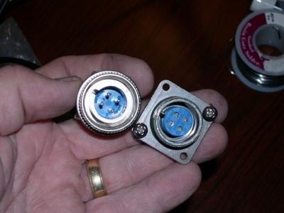
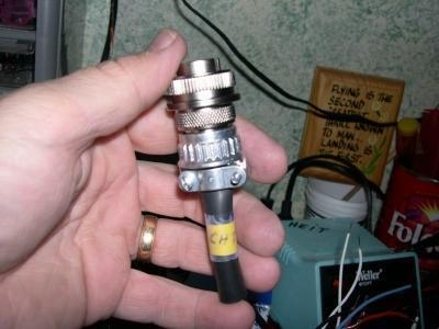
Photo 1: This shows the cannon plug being soldered. When soldering the wires to the plug connectors, tin the leads, and trim them to about 1/4" for fitting to the spade on the back side of the plug. The barrel clamp has been fitted over the wiring, and is marked with the function of that plug. In this case, the CHT wires are the point being connected by this particular plug. Note the use of shrink tubing on the individual wires being soldered into the plug base. This keeps the wires from shorting out to one another inside the barrel connection.Photo 2: Cannon plugs have a male [Left] and a female [right] connection. By using these on the panel harness assembly, I can remove the panel at a later date for repairs, inspection or modifications. Photo 3: The completed cannon plug assembly ... the yellow band is a shrink tube I put on the plug cover to identify the function of the plug. I have written in ink "CHT" [Cylinder Head Temprature] to indicate its function, and covred it with a tape to protect it. I wanted to get some better close in shots of the soldering but my camera just won't cooperate.