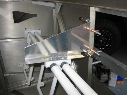
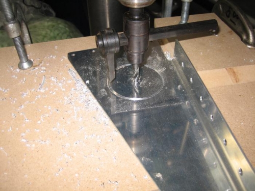
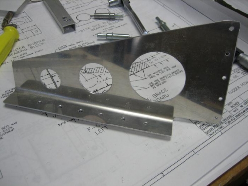
I installed the rudder pedal tubes and blocks to the stiffeners in the fusalage and bolted in place. Next I drilled the 2 holes in the center rudder bearing block to #10 as specified. Now I had to bandsaw the block in half right down the center across the two rudder pedal tube holes. I used a razor blade to clean the edges of the block halves. I laid one block half on top of the rudder pedal tube assembly at midpoint. In order for the F-6118 rudder pedal brace to fit I have to trim the bottom flange back 1 3/8" so it will clear the firewall recess. I did this using my band saw. I radiused the end of the cut and deburred the edges. Next I clamped the F-6118 rudder pedal brace to the F-601N-L firewall stiffener so that the bottom flange of the stiffener rested on top of the block. I marked where I needed to drill the holes through the brace and firewall stiffener. I also marked the two holes for the center brace block. I drilled 5 #30 holes through the brace and stiffener. I removed the brace and deburred the holes. I drilled one of the block to brace holes to #10 and then used the jig I had made earlier to drill the remaining 5 holes. Last step was to make lightening holes in the brace. I used my drill press to cut the 3 holes of various sizes. I deburred all the edges and set the pieces aside for later priming.